Hyundai i-30: Charging System / Battery

Hyundai i30 (PD) 2018-2024 Service Manual / Engine Electrical System / Charging System / Battery

Description and operation
Description
AGM Battery
AGM battery is used for especially heavy load on the vehicle network depending on equipment and requirements. AGM stands for Absorbent Glass Material Battery; that is absorbent glass fibre fleece. AGM batteries are fitted in models with electrical loads/consumers which have a high energy demand.The constantly increasing energy demand of modern vehicle electrical systems calls for ever more powerful battery solutions.The power consumption is considerable even when the vehicle is parked.The somewhat higher price compared with a battery of similar size is fully balanced by the following benefits :
Significantly longer service life
Increased starting reliability at low temperatures
100 % freedom from maintenance
Low risk in event of an accident (reduced risk to the environment)
[AGM70L]

  
After disconnecting then reconnecting the battery negative cable, reset some parts that require the reset procedures.
(Refer to Body Electrical System - "General Information")
CMF Battery
The CMF (Closed Maintenance Free) battery is, as the name implies, totally maintenance free and has no removable battery cell caps.
The CMF (Closed Maintenance Free) battery does not require water replenishment for the repair.
The battery is completely sealed, except for small vent holes in the cover.
[CMF60L]

[CMF45L]

Specifications
Specification
▷ CMF60L-DIN
Item
Specification
Model type
CMF60L-DIN
Capacity [20HR/5HR] (AH)
60 / 48
Cold Cranking Amperage (A)
550 (SAE) / 440 (EN)
Reserve Capacity (Min)
92
Specific Gravity
1.27 ~ 1.29 [25°C (77°F)]
Voltage (V)
12

▷ AGM70L-DIN
Item
Specification
Model type
AGM70L-DIN
Capacity [20HR/5HR] (AH)
70 / 56
Cold Cranking Amperage (A)
760 (SAE) / 760 (EN)
Reserve Capacity (Min)
120
Specific Gravity
1.30 ~ 1.32 [25°C (77°F)]
Voltage (V)
12

▷ CMF45L-DIN
Item
Specification
Model type
CMF45L-DIN
Capacity [20HR/5HR] (AH)
45 / 36
Cold Cranking Amperage (A)
410 (SAE) / 410 (EN)
Reserve Capacity (Min)
80
Specific Gravity
1.27 ~ 1.29 [25°C (77°F)]
Voltage (V)
12

  
Model type description

Cold Cranking Ampere (CCA) : A rating used in the battery industry to define a battery's ability to start an engine in cold temperatures.
The rating is the number of amps a new, fully charged battery can deliver at -18°C (-0.4°F) for 30 seconds, while maintaining a voltage of at least 7.2 volts for a 12 volt battery.
The higher the CCA rating, the greater the starting power of the battery.
RESERVE CAPACITY (RC) : A battery industry rating, defining a battery's ability to power a vehicle with an inoperative alternator or fan belt.
The rating is the number of minutes a battery at 26.7°C (80°F) can be discharged at 25 amps and maintain a voltage of 10.5 volts for a 12 volt battery.
The higher the reserve rating, the longer your vehicle can operate should your alternator or fan belt fail.
  
BCI Type
Capacity
(5HR/20HR)
Length
Width
Height
Total Height
L (mm)
W (mm)
T (mm)
TH (mm)
28/35
188 - 192
126 - 130
198 - 202
218 - 222
32/40
194 - 198
133 - 137
199 - 203
223 - 227
36/45
203 - 207
173 - 177
200 - 204
221 - 225
44/55
213 - 217
173 - 177
198 - 202
218 - 222
48/60
228 - 232
173 - 177
200 - 204
221 - 225
54/68
258 - 262
173 - 177
198 - 202
220 - 224
56/70
258 - 262
173 - 177
198 - 202
223 - 227
64/80
274 - 278
170 - 174
198 - 202
221 - 225
70/88
349 - 353
172 - 176
186 - 200
183 - 187
72/90
300 - 304
170 - 174
200 - 204
221 - 225
76/95
294 - 298
172 - 176
198 - 202
220 - 224
80/100
326 - 330
170 - 174
203 - 207
225 - 229

[DIN Type]
Capacity
(5HR/20HR)
Length
Width
Height
Total Height
L (mm)
W (mm)
T (mm)
TH (mm)
36/45
205 - 207
173 - 175
164 - 168
188 - 190
48/60
205 - 207
173 - 175
164 - 168
188 - 190
54/68
205 - 207
173 - 175
164 - 168
188 - 190
64/80
205 - 207
173 - 175
164 - 168
188 - 190
72/90
205 - 207
173 - 175
164 - 168
188 - 190
80/100
205 - 207
173 - 175
164 - 168
188 - 190
88/110
205 - 207
173 - 175
164 - 168
188 - 190

[AGM DIN Type]
Capacity
(5HR/20HR)
Length
Width
Height
Total Height
L (mm)
W (mm)
T (mm)
TH (mm)
40/50
205 - 207
173 - 175
164 - 168
188 - 190
48/60
227 - 229
173 - 175
164 - 168
188 - 190
56/70
276 - 278
173 - 175
164 - 168
188 - 190
64/80
312 - 314
173 - 175
164 - 168
188 - 190
72/90
351 - 353
173 - 175
164 - 168
188 - 190
84/105
392 - 394
173 - 175
164 - 168
188 - 190

Repair procedures
Removal
Battery
1.
Turn the ignition switch OFF and disconnect the battery (-) terminal (A).
Tightening torque :
7.8 - 9.8 N.m (0.8 - 1.0 kgf.m, 5.8 - 7.2 Ib-ft)

2.
Disconnect the battery (+) terminal (A).
Tightening torque :
7.8 - 9.8 N.m (0.8 - 1.0 kgf.m, 5.8 - 7.2 Ib-ft)

3.
Remove the battery mouting bracket.
Tightening torque :
7.8 - 11.8 N.m (0.8 - 1.2 kgf.m, 5.8 - 8.7 Ib-ft)
4.
Remove the battery (A).

Battery Tray
1.
Remove the battery.
2.
Remove the air cleaner assembly.
(Refer to Engine Mechanical System - "Air Cleaner")
3.
Remove the engine control module (ECM).
(Refer to Engine Control / Fuel System - "Engine Control Module (ECM)")
4.
Remove the battery tray (A).
Tightening torque :
8.8 - 13.7 N.m (0.9 - 1.4 kgf.m, 6.5 - 10.1 Ib-ft)

Installation
1.
Install in the reverse order of removal.
  
When installing the battery, fix the mounting bracket on the tray correctly.
  
After disconnecting then reconnecting the battery negative cable, reset some parts that require the reset procedures.
(Refer to Body Electrical System - "General Information")
  
ISG (Idle stop & go) system equipped vehicle always use the AGM battery only. If flooded battery has installed, this can potentially lead to engine electrical trouble or ISG system error.
Replace same capacity of the AGM battery.
  
Do not open the AGM battery.
The AGM battery must not be opened under any circumstances as the introduction of oxygen from the air will cause the battery to lose its chemical equilibrium and rendered non-operational.
Inspection
Battery Condition
Check the battery for damage or deformation. If severe damage, deformation or leakage is found, replace the battery.
Vehicle parasitic current inspection
[Using the Ammeter]
1.
Turn the all electric devices OFF, and then turn the ignition switch OFF.
2.
Close all doors except the engine hood, and then lock all doors.
(1)
Disconnect the hood switch connector.
(2)
Close the trunk lid.
(3)
Close the doors or remove the door switches.
3.
Wait a few minutes until the vehicle’s electrical systems go to sleep mode.
  
For an accurate measurement of a vehicle parasitic current, all electrical systems should go to sleep mode. (It takes at least one hour or at most one day.) However, an approximate vehicle parasitic current can be measured after 10-20 minutes.
4.
Connect an ammeter in series between the battery (-) terminal and the ground cable, and then disconnect the clamp from the battery (-) terminal slowly.
  
Be careful that the lead wires of an ammeter do not come off from the battery (-) terminal and the ground cable to prevent the battery from being reset. In case the battery is reset, connect the battery cable again, and then start the engine or turn the ignition switch ON for more than 10 sec. Repeat the procedure from No. 1.
To prevent the battery from being reset during the inspection,
1)
Connect a jump cable between the battery (-) terminal and the ground cable.
2)
Disconnect the ground cable from the battery (-) terminal.
3)
Connect an ammeter between the battery (-) terminal and the ground cable.
4)
After disconnecting the jump cable, read the current value of the ammeter.

5.
Read the current value of the ammeter.
If the parasitic current is over the limit value, search for abnormal circuit by removing a fuse one by one and checking the parasitic current.
Reconnect the suspected parasitic currentdraw circuit fuse only and search for suspectedunit by removing the component connected with thecircuit one by one until the parasitic draw dropsbelow limit value.
Limit value (after 10 - 20 min.) : Below 50 mA
[Using the Clamp type Ammeter]
1.
Turn the all electric devices OFF, and then turn the ignition switch OFF.
2.
Close all doors except the engine hood, and then lock all doors.
(1)
Disconnect the hood switch connector.
(2)
Close the trunk lid.
(3)
Close the doors or remove the door switches.
3.
Wait a few minutes until the vehicle’s electrical systems go to sleep mode.
  
For an accurate measurement of a vehicle parasitic current, all electrical systems should go to sleep mode. (It takes at least one hour or at most one day.) However, an approximate vehicle parasitic current can be measured after 10-20 minutes.
4.
Install the clamp type ammerter on battery negative (-) terminal.

5.
Read the current value of the ammeter.
If the parasitic current is over the limit value, search for abnormal circuit by removing a fuse one by one and checking the parasitic current.
Reconnect the suspected parasitic currentdraw circuit fuse only and search for suspectedunit by removing the component connected with thecircuit one by one until the parasitic draw dropsbelow limit value.
Limit value (after 10 - 20 min.) : Below 50 mA
The Micro 570 Analyzer
The Micro 570 Analyzer provides the ability to test the charging and starting systems, including the battery, starter and alternator.
  
※ Because of the possibility of personal injury, always use extreme caution and appropriate eye protection when working with batteries.
※ When charging battery by test result, Battery must be fully charged.
To get accurate test result, battery surface voltage must have subsided ahead before test when you test battery after charged. (See following Battery Test Results)

Keypad
The Micro 570 button on the key pad provide the following functions :

Battery Test Procedure
1.
Connect the tester to the battery.
Red clamp to battery positive (+) terminal.
Black clamp to battery negative (-) terminal.

  
Connect clamps securely. If "CHECK CONNECTION" message is displayed on the screen, reconnect clamps securely.
2.
The tester will ask if the battery is connected "IN-VEHICLE" or "OUT-OF-VEHICLE". Make your selection by pressing the arrow buttons; then press ENTER.

3.
Select CCA and press the ENTER button.

  
CCA : Cold cranking amps, is an SAE specification for cranking batteried at -0.4°F (-18°C).
4.
Set the CCA value displayed on the screen to the CCA value marked on the battery label by pressing up and down buttons and press ENTER.

  
The battery ratings (CCA) displayed on the tester must be identical to the ratings marked on battery label.
5.
The tester will conduct battery test.

6.
The tester displays battery test results including voltage and battery ratings.
Refer to the following table and take the appropriate action as recommended by the Micro 570.

Battery Test Results
Result On Printer
Remedy
GOOD BATTERY
No action is required.
GOOD RECHARGE
Battery is in a good state.
Recharge the battery and use.
※ You have to follow instruction below when you charge battery and retest, otherwise test result can be inaccurate. (See ‘Charge and Retest method after battery charge’ below.)
CHARGE & RETEST
Battery is not charged properly.
Charge and test the battery again.
※ You have to follow instruction below when you charge battery and retest, otherwise test result can be inaccurate. (See ‘Charge and Retest method after battery charge’ below.)
REPLACE BATTERY
Replace battery and recheck the charging system.
Improper connection between battery and vehicle cables may cause "REPLACE BATTERY". Retest the battery after removing cables and connecting the tester to the battery terminal directly prior to replacing the battery.
BAD CELL-REPLACE
Charge and retest the battery.
If the Micro 570 recommends "REPLACE BATTERY", replace the battery and recheck the charging system.

[Charge and Retest method after battery charge]
Battery charge
Set battery charger to ‘Auto Mode’ (The Mode that charging current drops as the battery charges.) and charge battery until charging current down close to zero or the charger alerts you with an alarm when charge is complete.
(Minimum charging time recommended: More than 3 hours with Auto Mode that explained above)
If battery is not fully charged, battery surface voltage will be high while the amount of current charged (CCA) in battery is low. If you measure the battery under this condition, tester may misjudge that battery sulfation occurred because the amount of current in battery is too low in comparison with battery voltage.
* Surface voltage: When battery is charged electrolyte temperature increases and chemical reaction become active resulting in an excessive increase of battery voltage.
It is known that it takes approximate one day to subside this increased surface voltage completely.
Battery Test after charge
Do not test battery right after the charge. Test battery after battery surface voltage has subsided as instructed in the following procedure.
(1)
When battery charge is complete, install the battery in the vehicle.
(2)
Put IG key to ON position and turn on head lamp with low beam, and wait 5 minutes. (Discharge for 5 minutes)
(3)
Turn off the head lamp and IG key, and wait 5 minutes. (Waiting for 5 minutes)
(4)
Remove +, - cable from the battery and test battery.
  
Whenever filing a claim for battery, the print out of the battery test results must be attached.
Starter Test Procedure
7.
After the battery test, press ENTER immediately for the starter test.

8.
Start the engine.

9.
Cranking voltage and starter test results will be displayed on the screen.
Refer to the following table and take the appropriate action as recommended by the Micro 570.

Starter Test Results
Result On Printer
Remedy
CRANKING VOLTAGE NORMAL
System shows a normal starter draw.
CRANKING VOLTAGE LOW
Cranking voltage is lower than normal level.
Check starter.
CHARGE BATTERY
The state of battery charge is too low to test.
Charge the battery and retest.
REPLACE BATTERY
Replace battery.
If the vehicle is not started though the battery condition of "GOOD BATTERY" is displayed, check wiring for open circuit, battery cable connection, starter and repair or replace as necessary.
If the engine does crank, check fuel system.

  
When testing the vehicle with old diesel engines, the test result will not be favorable if the glow plug is not heated. Conduct the test after warming up the engine for 5 minutes.
Charging System Test Procedure
10.
Press ENTER to begin charging system test.

11.
The tester displays the actual voltage of alternator.
Press ENTER to continue.

12.
Turn off all electrical load and rev engine for 5 seconds with pressing the accelerator pedal. (Follow the instructions on the screen)

13.
The message that engine RPM is detected will be displayed on the screen. Press ENTER to continue.

14.
If the engine RPM is not detected, press ENTER after revving engine.

15.
The tester will conduct charging system test during loads off.

16.
Turn on electrical loads (air conditioner, lamps, audio and etc). Press ENTER to continue.

17.
The tester will conduct charging system test during loads on.

18.
Rev engine for 5 seconds with pressing the accelerator pedal. (Follow the instructions on the screen)

19.
The message that engine RPM is detected will be displayed on the screen. Press ENTER to continue.

20.
If the engine RPM is not detected, press ENTER after revving engine.

21.
Turn off electrical loads (air conditioner, lamps, audio and etc). Turn the engine off.

22.
Charging voltage and charging system test results will be displayed on the screen.
Shut off engine end disconnect the tester clamps from the battery. Refer to the following table and take the appropriate action as recommended by the Micro 570.

Charging System Test Results
Result On Printer
Remedy
CHARGING SYSTEM NORMAL / DIODE RIPPLE NORMAL
Charging system is normal.
NO CHARGING VOLTAGE
Alternator does not supply charging current to battery.
Check belts, connection between alternator and battery and replace belts or cable or alternator as necessary.
LOW CHARGING VOLTAGE
Alternator does not supply charging current to battery and electrical load to system fully.
Check belts and alternator and replace as necessary.
HIGH CHARGING VOLTAGE
The voltage from alternator to battery is higher than normal limit during voltage regulating.
Check connection and ground and replace regulator as necessary.
Check electrolyte level in the battery.
EXCESS RIPPLE DETECTED
One or more diodes in the alternator is not functioning properly.
Check alternator mounting and belts and replace as necessary.

The MDX-670P Analyzer
The MDX-670P battery conductance and electrical system analyzer tests batteries as well as starting and charging systems for vehicle.
It displays the test results in seconds and features a built-in printer to provide a copy of the results.

  
1)
Because of the possibility of personal injury, always use extreme caution and appropriate eye protection when working with batteries.
2)
When charging battery by test result, Battery must be fully charged. To get accurate test result, battery surface voltage must have subsided ahead before test when you test battery after charged. (See following Battery Test Results)
  
When testing the vehicle with old diesel engines, the test result will not be favorable if the glow plug is not heated. Conduct the test after warming up the engine for 5 minutes.

1.
Connect the red clamp to the positive (+) terminal and the black clamp to the negative (–) terminal.
  
For a proper connection, rock the clamps back and forth. The tester requires that both sides of each clamp be firmly connected before testing. A poor connection will produce a CHECK CONNECTION or WIGGLE CLAMPS message. If the message appears, clean the terminals and reconnect the clamps.
2.
Scroll to and select IN VEHICLE or OUT OF VEHICLE for a battery not connected to a vehicle.

  
Following an IN VEHICLE test you will be prompted to test the starting and charging systems.
3.
Scroll to and select REGULAR FLOODED, AGM FLAT PLATE, or AGM SPIRAL where applicable.

  
If the vehicle equipped with ISG function, select the AGM FLAT PLATE.
4.
Scroll to and select the battery’s rating system.
  
Mostly, the CCA value is marked on the battery label, but sometimes marked EN or SEA value. Select one of them.

CCA : Cold Cranking Amps, as specified by SAE. The most common rating for cranking batteries at 0°F (-17.8 °C).
EN : Europe-Norm
SAE : Society of Automotive Engineers, the European labeling of CCA
5.
Set the selected rating value displayed on the screen to the value marked on the battery label by pressing up and down arrow buttons.

6.
Press ENTER to start test.

7.
After several seconds the tester displays the decision on the battery’s condition and the measured voltage. The tester also displays your selected battery rating and the rating units.

Battery Test Results
Result On Printer
Remedy
GOOD BATTERY
No action is required.
GOOD RECHARGE
Battery is in a good state. Recharge the battery and use.
※ You have to follow instruction below when you charge battery and retest, otherwise test result can be inaccurate. (See ‘Charge and Retest method after battery charge’ below.)
CHARGE & RETEST
Battery is not charged properly.
Charge and test the battery again.
※ You have to follow instruction below when you charge battery and retest, otherwise test result can be inaccurate. (See ‘Charge and retest method after battery charge’ below.)
REPLACE BATTERY
Replace battery and recheck the charging system.
Improper connection between battery and vehicle cables may cause "REPLACE BATTERY", retest the battery after removing cables and connecting the tester to the battery terminal directly prior to replacing the battery.
BAD CELLREPLACE
Charge and retest the battery.
If recommends "REPLACE BATTERY", replace the battery and recheck the charging system.

[Charge and Retest method after battery charge]
Battery charge
Set battery charger to ‘Auto Mode’ (The Mode that charging current drops as the battery charges.) and charge battery until charging current down close to zero or the charger alerts you with an alarm when charge is complete.(Minimum charging time recommended: More than 3 hours with Auto Mode that explained above)
If battery is not fully charged, battery surface voltage will be high while the amount of current charged (CCA) in battery is low. If you measure the battery under this condition, tester may misjudge that battery sulfation occurred because the amount of current in battery is too low in comparison with battery voltage.
* Surface voltage: When battery is charged electrolyte temperature increases and chemical reaction become active resulting in an excessive increase of battery voltage.
It is known that it takes approximate one day to subside this increased surface voltage completely.
Battery Test after charge
Do not test battery right after the charge. Test battery after battery surface voltage has subsided as instructed in the following procedure.
(1)
When battery charge is complete, install the battery in the vehicle.
(2)
Put IG key to ON position and turn on head lamp with low beam, and wait 5 minutes. (Discharge for 5 minutes)
(3)
Turn off the head lamp and IG key, and wait 5 minutes. (Waiting for 5 minutes)
(4)
Remove +, - cable from the battery and test battery.
  
For an in-vehicle test, the display alternates between the test results and the message "PRESS FOR STARTER TEST".
  
Before starting the test, inspect the alternator drive belt. A belt that is glazed or worn, or lacks the proper tension, will prevent the en¬gine from achieving the rpm levels needed for the test.
8.
Press the ENTER button to proceed with the starter test.

9.
Start the engine when prompted.

10.
The tester displays the decision on the starter system, cranking voltage, and cranking time in milliseconds.

Starter Test Results
Result On Printer
Remedy
CRANKING VOLTAGE NORMAL
System shows a normal starter draw.
CRANKING VOLTAGE LOW
Cranking voltage is lower than normal level.
Check starter.
CHARGE BATTERY
The state of battery charge is too low to test.
Charge the battery and retest.
REPLACE BATTERY
Replace battery.
If the vehicle is not started though the battery condition of "GOOD BATTERY" is displayed, check wiring for open circuit, battery cable connection, starter and repair or replace as necessary.
If the engine does crank, check fuel system.

  
For an in-vehicle test, the display alternates between the test results and the message "PRESS FOR CHARGING TEST.
Step 3 : Charging System Test
11.
Press the ENTER button to proceed with the charging test.

12.
Rev the engine with loads off. (Following the on-screen prompts)

13.
The message that engine RPM is detected will be displayed on the screen, idle the engine.

14.
Turn on electrical loads (air conditioner, lamps, audio and etc). Press ENTER to continue.

15.
Turn on electrical loads (air conditioner, lamps, audio and etc). Press ENTER to continue.

16.
The message that engine RPM is detected will be displayed on the screen, idle the engine.

17.
Turn off loads and engine.

18.
The Charging System decision is displayed at the end of the procedure.

Result On Printer
Remedy
NO PROBLEMS
System is showing normal output from the alternator.
NO OUTPUT
No alternator output detected.
Check all connections to and from the alternator, especially the connection to the battery. If the connection is loose or heavily corroded, clean or replace the cable and retest.
If the belts and connections are in good working condition, replace the alternator. (Older vehicles use external voltage regulators, which may require only replacement of the voltage regulator.)
LOW OUTPUT
Alternator does not supply charging current to battery and electrical load to system fully.
Check belts and alternator and replace as necessary.
HIGH OUTPUT
The voltage from alternator to battery is higher than normal limit during voltage regulating.
Check connection and ground and replace regulator as necessary.
Check electrolyte level in the battery.
EXCESSIVE RIPPLE
The voltage from alternator to battery is higher than normal limit during voltage regulating.
Check alternator mounting and belts and replace as necessary.
CHARGE BATTERY
The starter voltage is low and the battery is discharged. Fully charge the battery and repeat the starter system test.
REPLACE BATTERY
Battery must be replaced before the starting system can be tested.

19.
Press the BACK/PRINT button to print the test results or MENU to return to the Options Menu.
Cleaning
1.
Make sure that the ignition switch and all accessories are in the OFF position.
2.
Disconnect the battery cables (negative first).
3.
Remove the battery from the vehicle.
  
Care should be taken in the event the battery case is cracked or leaking, to protect your skin from the electrolyte.
Heavy rubber gloves (not the household type) should be wore when removing the battery.

4.
Inspect the battery tray for damage caused by the loss of electrolyte. If acid damage is present, it will be necessary to clean the area with a solution of clean warm water and baking soda. Scrub the area with a stiff brush and wipe off with a cloth moistened with baking soda and water.
5.
Clean the top of the battery with the same solution as described above.
6.
Inspect the battery case and cover for cracks. If cracks are present, the battery must be replaced.
7.
Clean the battery posts with a suitable battery post tool.
8.
Clean the inside surface of the terminal clamps with a suitable battery cleaning tool. Replace damaged or frayed cables and broken terminal clamps.
9.
Install the battery in the vehicle.
10.
Connect the cable terminals to the battery post, making sure tops of the terminals are flush with the tops of the posts .
11.
Tighten the terminal nuts securely.
12.
Coat all connections with light mineral grease after tightening.
  
When batteries are being charged, an explosive gas forms beneath the cover of each cell. Do not smoke near batteries being charged or which have recently been charged. Do not break live circuit at the terminals of batteries being charged.
A spark will occur when the circuit is broken. Keep open flames away from battery.

    DC DC converter

    Description and operation Description Due to the considerably more frequent occurrence of starting operations, the electrical load that occurs often leads to voltage dips in the vehicle network...

    Battery Sensor

    Description and operation Description Vehicles have many control units that use more electricity. These units control their own system based on information from various sensors...

    Other information:

    Hyundai i30 (PD) 2018-2024 Owner's Manual: Rear fog lamp


    Vehicle with front fog lamp To turn on the rear fog lamp: Position the light switch in the position lamp position, turn the light switch (1) to the front fog lamp position, and then turn the light switch (1) to the rear fog lamp position. To turn the rear fog lamps off, do one of the following: Turn off the position light switch...

    Hyundai i30 (PD) 2018-2024 Service Manual: Front Stabilizer Bar


    Repair procedures Removal 1. Loosen the wheel nuts slightly. Raise the vehicle, and make sure it is securely supported. 2. Remove the front wheel and tire (A) from the front hub...

    Categories

    Gauges and meters

    Speedometer

    Hyundai i30. Gauges and meters

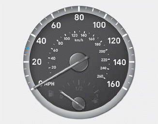
    The speedometer indicates the speed of the vehicle and is calibrated in kilometers per hour (km/h) and/or miles per hour (MPH).
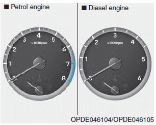
    Tachometer

    Hyundai i30. Gauges and meters

    read more


    Copyright © 2024 www.hi30.net