Hyundai i-30: Cylinder Head Assembly / Cylinder Head
Repair procedures
|
1. |
Remove the engine cover.
(Refer to Engine and Transaxle Assembly - "Engine Cover")
|
|
2. |
Remove the air duct and air cleaner assembly.
(Refer to Intake and Exhasut System - "Air Cleaner")
|
|
3. |
Remove the battery.
(Refer to Engine Electrical System - "Battery")
|
|
4. |
Remove the engine control module (ECM).
(Refer to Engine Control / Fuel System - "Engine Control Module (ECM)")
|
|
5. |
Remove the battery tray.
(Refer to Engine Electrical System - "Battery")
|
|
6. |
Remove the engine room under cover.
(Refer to Engine and Transaxle Assembly - "Engine Room Under Cover")
|
|
7. |
Drain the coolant.
(Refer to Cooling System - "Coolant")
|
|
8. |
Disconnect the fuel hose (A) and purge control solenoid valve (PCSV)
hose (B).
|
|
9. |
Remove the cylinder head cover.
(Refer to Cylinder Heae Assembly - "Cylinder Head Cover")
|
|
10. |
Remove the timing chain.
(Refer to Timing System - "Timing Chain")
|
|
11. |
Remove the intake manifold.
(Refer to Intake and Exhaust System - "Intake Manifold")
|
|
12. |
Remove the exhaust manifold.
(Refer to Intake and Exhaust System - "Exhaust Manifold")
|
|
13. |
Remove the ITM (Intergrated Thermal Management).
(Refer to Cooling System - "ITM (Intergrated Thermal Management).")
|
|
14. |
Remove the heater pipe.
(Refer to Cooling System - "Water Temperature Control Assembly")
|
|
15. |
Remove the MHSG
(Refer to Engine Electrical System - 'Mild Hybrid Starter Generator(MHSG)")
|
|
16. |
Remove the delivery pipe.
(Refer to Engine Control/Fuel System -"Delivery Pipe")
|
|
17. |
Remove the vacuum pump.
(Refer to Brake System - "Vacuum Pump")
|
|
18. |
Remove the CVVT & camshaft.
(Refer to Cylinder Head Assembly - "CVVT & Camshaft")
|
|
19. |
Remove the CVVD & camshaft.
(Refer to Cylinder Head Assembly - "CVVD Assembly")
|
|
20. |
Remove the camshaft position sensor (A).
|
|
21. |
Remove the cam carrier (A).
|
|
22. |
Remove the hydraulic lash adjuster (HLA) (A) and the swing arm (B).
|
• |
The HLA and swing arm should be kept together as pairs
during storage after removal and reinstallation.
|
|
|
|
23. |
Remove the spark plugs.
(Refer to Engine Electrical System - "Spark Plug")
|
|
24. |
Remove the cylinder head.
|
(1) |
Using bit socket (12PT), uniformly loosen and remove the cylinder
head bolts, in several passes, in the sequence as shown.
|
• |
Head warpage or cracking could result from removing
bolts in an incorrect order.
|
|
|
|
(2) |
Lift the cylinder head (A) from the dowels on the cylinder block
and place the cylinder head on wooden blocks on a bench.
|
|
(3) |
Remove the cylinder head gasket (B).
|
|
| •
|
Identify, valves and valve springs as they are removed so that
each item can be reinstalled in its original position.
|
|
|
1. |
Remove the valves.
|
(1) |
Using the SST (09222-3K000, 09222-3K100), press the valve spring
and remove retainer lock (A).
|
• |
Do not press valve retainer more than 9mm (0.35
in.)
|
|
|
|
(2) |
Remove the spring retainer (B).
|
|
(3) |
Remove the valve spring (C).
|
|
(4) |
Remove the valve (E).
|
|
(5) |
Using the pliers, remove the valve stem seal (D).
|
|
(6) |
Remove the valve seat.
|
• |
Do not reuse old valve stem seals.
|
|
|
|
Cylinder Head
|
1. |
Inspect for flatness.
Using a precision straight edge and feeler gauge, measure the surface
contacting cylinder block and the manifolds for warpage.
|
Flatness of cylinder head gasket surface
Standard : Less than 0.05 mm (0.0020 in)
Less than 0.02 mm (0.0008 in) / 100 x 100
Flatness of manifold gasket surface
Standard : Less than 0.1 mm (0.0039 in)
|
|
|
2. |
Inspect for cracks.
Check the combustion chamber, intake ports, exhaust ports and cylinder
block surface for cracks. If cracked, replace the cylinder head.
|
Valve and Valve Spring
|
1. |
Inspect valve stems and valve guides.
|
(1) |
Using a caliper gauge, measure the inside diameter of the valve
guide.
|
Valve guide I.D.
Intake :45.8 - 46.2 mm (1.8031 - 1.8188 in.)
Exhaust : 45.8 - 46.2 mm (1.8031 - 1.8188 in.)
|
|
|
(2) |
Using a micrometer, measure the diameter of the valve stem.
|
Valve stem O.D.
Intake : 5.460 - 5.475 mm (0.2149 - 0.2155 in.)
Exhaust : 5.443 - 5.455 mm (0.2142 - 0.2247 in.)
|
|
|
(3) |
Subtract the valve stem diameter measurement from the valve
guide inside diameter measurement.
|
Valve stem-to-guide clearance
Intake : 0.025 - 0.052 mm (0.00098 - 0.00204 in.)
Exhaust : 0.055 - 0.069 mm (0.00216 - 0.00271 in.)
|
|
|
|
2. |
Inspect valves.
|
(1) |
Check the valve is ground to the correct valve face angle.
|
Valve face angle :
Intake/Exhaust : 45.25° - 45.75°
|
|
|
(2) |
Check that the surface of the valve for wear. If the valve face
is worn, replace the valve.
|
|
(3) |
Check the valve head margin thickness. If the margin thickness
is less than minimum, replace the valve.
|
Margin
Intake :0.85 - 1.15 mm (0.0334 - 0.0452 in.)
Exhaust : 1.15 - 1.45 mm (0.0452 - 0.0570 in.)
|
|
|
(4) |
Check the valve length.
|
Length
Intake :45.8 - 46.2 mm (1.8031 - 1.8188 in.)
Exhaust : 45.8 - 46.2 mm (1.8031 - 1.8188 in.)
|
|
|
(5) |
Check the surface of the valve stem tip for wear. If the valve
stem tip is worn, replace the valve.
|
|
|
3. |
Inspect valve seats.
|
(1) |
Check the valve seat for evidence of overheating and improper
contact with the valve face.
If the valve seat is worn, replace cylinder head.
|
|
(2) |
Before reconditioning the seat, check the valve guide for wear.
If the valve guide is worn, replace cylinder head.
|
|
(3) |
Recondition the valve seat with a valve seat grinder or cutter.
The valve seat contact width should be within specifications
and centered on the valve face.
|
Valve seat contact width
Intake : 0.85 - 1.15 mm ( 0.0334 - 0.0452 in)
Exhaust : 1.35 - 1.65 mm (0.0531 - 0.0649 in)
Valve seat angle :
Intake / Exhaust : 44.75° - 45.10°
|
|
|
|
4. |
Inspect valve springs.
|
(1) |
Using a steel square, measure the out-of-square of the valve
spring.
|
|
(2) |
Using vernier calipers, measure the free length of the valve
spring.
|
Intake Valve spring
Standard
Free height : 47.9 mm (1.8858 in)
Load :
16.7 ± 0.8 kgf.m / 35.5 mm (36.81 ± 1.76 lb / 1.3976
in.)
30.2 ± 1.4 kgf.m / 26.8 mm (65.57 ± 3.08 lb / 1.0905
in.)
Out of squareness : 1.5° MAX
Exhaust Valve spring
Standard
Free height : 54.3 mm (2.1377 in.)
Load :
23.5 ± 1.1 kgf.m / 35.5 mm (51.81 ± 2.42 lb / 1.3976
in.)
36.2 ± 1.2 kgf.m / 27.7 mm (79.81 ± 2.64 lb / 1.0905
in.)
Out of squareness : 1.5° MAX
|
|
|
HLA (Hydraulic Lash Adjuster)
With the HLA filled with engine oil, hold A and press B by hand. If B moves,
replace the HLA.
Problem
|
Possible cause
|
Action
|
1. Temporary noise when starting a cold engine
|
Normal
|
This noise will disappear after the oil in the engine reaches the normal
pressure.
|
2. Continuous noise when the engine is started after parking more than 48
hours
|
Oil leakage of the high pressure chamber on the HLA, allowing air to get
in
|
Noise will disappear within 15 minutes when engine runs at 2000-3000 rpm.
If it doesn’t disappear, refer to step 7 below.
|
3. Continuous noise when the engine is first started after rebuilding cylinder
head
|
Insufficient oil in cylinder head oil gallery
|
4. Continuous noise when the engine is started after excessively cranking
the engine by the starter motor or band
|
| •
|
Oil leakage of the high-pressure chamber in the HLA, allowing
air to get in
|
| •
|
Insufficient oil in the HLA
|
|
5. Continuous noise when the engine is running after changing the HLA
|
|
• |
Do not run engine at a speed higher than 3000 rpm, as
this may damage the HLA.
|
|
|
6. Continuous noise during idle after high engine speed
|
Engine oil level too high or too low
|
| •
|
Drain or add oil as necessary.
|
|
Excessive amount of air in the oil at high engine speed
|
Check oil supply system.
|
Deteriorated oil
|
Check oil quality.
If deteriorated, replace with specified type.
|
7. Noise continues for more than 15 minutes
|
Low oil pressure
|
Check oil pressure and oil supply system of each part of engine.
|
Faulty HLA
|
Remove the cylinder head cover and press HLA down by hand.
If it moves, replace the HLA.
|
| •
|
Thoroughly clean all parts to be assembled.
|
| •
|
Before installing the parts, apply fresh engine oil to all sliding
and rotating surfaces.
|
| •
|
Replace oil seals with new ones.
|
|
|
1. |
Install the valves.
|
(1) |
Using the SST (09222-G2100, 09222-G2200), push in a new valve
stem seal.
|
• |
Do not reuse old valve stem seals.
|
|
• |
Incorrect installation of the seal could result
in oil leakage past the valve guides.
|
|
|
|
(2) |
Install the valve seat.
|
|
(3) |
Install the valve spring and spring retainer.
|
• |
Place valve springs so that the cone shape side
is upward retainer side.
|
|
|
|
(4) |
Using the SST (09222-3K000, 09222-3K100), compress the spring
and install the retainer locks. After installing the valves,
ensure that the retainer locks are correctly in place before
releasing the valve spring compressor.
|
• |
When installing the SST, insert the front support
directly into the bolt hole on the cylinder
head.
|
|
|
• |
Do not press valve retainer more than 9 mm (0.35
in.).
|
|
|
|
(5) |
Lightly tap the end of each valve stem two or three times with
the wooden handle of a hammer to ensure proper seating of the
valve and retainer lock.
|
|
| •
|
Thoroughly clean all parts to be assembled.
|
| •
|
Always use a new head and manifold gasket.
|
| •
|
The cylinder head gasket is a metal gasket. Take care not to
bend it.
|
| •
|
Rotate the crankshaft, set the No.1 piston at TDC.
|
|
|
1. |
Install the cylinder head gasket.
|
(1) |
The sealant locations on cylinder head gasket, cylinder block
and cylinder head must be free of engine oil and etc.
|
|
(2) |
Apply sealant MS721-40AA on the cylinder block top surface (Refer
to below illustration) before assembling the cylinder head gasket.
|
Bead width : 2.0 - 3.0 mm (0.0787 - 0.1181 in)
|
|
|
(3) |
Install the cylinder head gasket (B) on the cylinder block.
|
• |
Be careful of the installation direction.
|
|
|
|
(4) |
Apply sealant MS721-40AA on the cylinder head gasket top surface
(Refer to below illustration) after assembling the cylinder
head gasket.
|
Bead width : 2.0 - 3.0 mm (0.0787 - 0.1181 in)
|
|
|
(5) |
Remove the extruded sealant after assembling the cylinder head
assembly.
|
|
|
2. |
Install the cylinder head assembly.
|
(1) |
Place the cylinder head assembly (A) quietly in order not to
damage the gasket with the bottom part of the end.
|
|
(2) |
Using SST (09221-4A000), tighten the cylinder head bolts and
plate washers, in several passes, in the sequence shown.
|
Tightening torque :
12.7 - 16.7 N.m (1.3 - 1.7 kgf.m, 9.4 - 12.3 lb-ft)
+ 140 - 145° + 140 - 145°
|
|
• |
Do not reuse the cylinder head bolts.
|
|
• |
Do not apply engine oil on the bolt threads
to achieve correct torque.
|
|
• |
Remove the extruded sealant within 5 minutes
after installing cylinder head bolts.
|
|
• |
The engine running or pressure test should not
be performed within 30minutes after installing
cylinder head bolts.
|
|
• |
Be careful not to change the installing position
of the preassembled washer bolts and non-preassembled
washer bolts.
|
|
• |
When installing the washer of the non-preassembled
washer bolts, the round and chamfer of washers
should be faced up.
|
|
|
|
|
3. |
Install the spark plugs.
(Refer to Engine Electrical System - "Spark Plug")
|
|
4. |
Install the hydraulic lash adjuster (HLA) (A) and the swing arm (B).
|
(1) |
When installing HLA, it should be held upright so that engine
oil in HLA may not spill and assured that dust does not adhere
to HLA.
|
|
(2) |
HLA should be inserted carefully to the cylinder head not to
spill engine oil.
If engine oil has spilled out of the lash adjuster, HLA bleeding
should be performed according to the below procedure.
HLA bleeding procedure
Stroke the lash adjuster in engine oil by pushing its cap 4
to 5 times while pushing the ball down slightly using a hard
steel wire. Be careful not to give the ball a hard push because
the ball weighs just several grams.
If installing with engine oil spilling out of the lash adjuster
and air in it, it might make an abnormal noise.
|
|
|
5. |
Place the cam carrier on the cylinder head.
|
(1) |
Remove the hardening sealant, oil, cleaning residue, foreign
materials gathered in the bottom of the cam carrier and on the
top of the cylinder head.
|
|
(2) |
Apply a continuous bead of liquid sealant to the bottom surface
of the cam carrier, as shown in the illustration.
|
Bead width : 2.0 - 3.0 mm (0.08 - 0.12 in.)
Sealant : MS 721-40 AA or AA0
|
|
|
(3) |
Install the cam carrier (A).
|
Tightening torque
18.6 - 22.6 N.m (1.9 - 2.3 kgf.m, 13.7 - 16.6 lb-ft)
|
|
• |
Tighten the cam carrier mounting bolts when
installing the cam carrier.
|
|
|
|
|
6. |
Install the other parts reverse order of removal.
|
• |
Refill engine with engine oil.
|
|
• |
Refill a radiator and a reservoir tank with engine coolant.
|
|
• |
Clean battery posts and cable terminals and assemble.
|
|
• |
Inspect for fuel leakage.
- After assembling the fuel line, turn on the ignition
switch (do not operate the starter) so that the fuel
pump runs for approximately two seconds and fuel line
pressurizes.
- Repeat this operation two or three times, then check
for fuel leakage at any point in the fuel line.
|
|
• |
Bleed air from the cooling system.
- Start engine and let it run until it warms up. (Until
the radiator fan operates 3 or 4 times.)
- Turn off engine. Check the coolant level and add coolant
if needed. This will allow trapped air to be removed
from the cooling system.
- Put the radiator cap on tightly, then run engine again
and check for leaks.
|
|
|
Description and operation
Description
CVVD (Continuous Variable Valve Duration) System is a device to control the
optimum open and close timing according to the driving mode by changing the
valve opening section...
Repair procedures
Removal And Installation
1.
Disconnect the battery negative terminal.
2.
Remove the engine cover...
Other information:
The severe weather conditions of
winter quickly wear out tyres and
cause other problems. To minimise
winter driving problems, you should
take the following suggestions:
Information
Summer tyres are equipped to provide
the best driving performance on dry
roads, varying according to specification...
Refrigerant System Service
Basics (R-134a)
Refrigerant Recovery
Use only service equipment that is U.L-listed and is certified to meet the requirements
of SAE J2210 to remove R-134a(R-134a) from the air conditioning system...
Categories
Seat belt warning
Driver’s seat belt warning
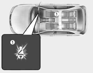
■ Instrument cluster
As a reminder to the driver, the seat
belt warning light will illuminate for
approximately 6 seconds each time
you turn the ignition switch ON
regardless of belt fastening.
read more


 CVVD Assembly
 Vacuum Pump