Hyundai i-30: Lighting System / Front Fog Lamps
Hyundai i30 (PD) 2018-2025 Service Manual / Body Electrical System / Lighting System / Front Fog Lamps
Repair procedures
| Removal |
Daytime Running Light (DRL)
| 1. |
Disconnect the negative (-) battery terminal.
|
| 2. |
Remove the front bumper.
(Refer to Body - "Front Bumper Cover")
|
| 3. |
Remove the front fog lamp assembly.
|
| 4. |
Remove the DRL assembly (A) after loosening the mounting screws.
|
| Installation |
Daytime Running Light (DRL)
| 1. |
Install the daytime running light assembly.
|
| 2. |
Install the front fog lamp assembly.
|
| 3. |
Connect the front fog lamp connector.
|
| 4. |
Install the front bumper.
|
| 5. |
Connect the negative (-) battery terminal.
|
 Rheostat
Components and components location
Components
Repair procedures
Inspection
1.
Disconnect the negative (-) battery terminal...
 License Lamps
Repair procedures
Removal
1.
Disconnect the negative (-) battery terminal.
2.
Using a screwdriver or remover, Separate the license lamp (A)...
Other information:
Hyundai i30 (PD) 2018-2025 Service Manual: Rear Bumper Assembly
Components and components location Component Location 1. Rear bumper assembly Repair procedures Replacement • Put on gloves to prevent hand injuries...
Hyundai i30 (PD) 2018-2025 Owner's Manual: Jack label
The actual Jack label in the vehicle may differ from the illustration. For more detailed specifications, refer to the label attached to the jack. 1. Model Name 2. Maximum allowable load 3. When using the jack, set your parking brake. 4. When using the jack, stop the engine...
Categories
- Manuals Home
- 3rd Generation i30 Owners Manual
- 3rd Generation i30 Service Manual
- EPB malfunction indicator
- Engine compartment
- To activate the ISG system
- New on site
- Most important about car
Tailgate
Opening the tailgate
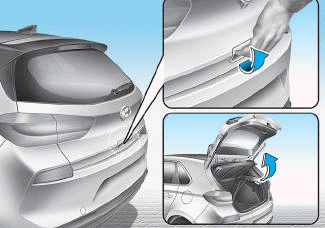
■ 5 Door, Wagon
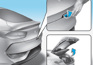
■ Fastback

Copyright © 2025 www.hi30.net