Hyundai i-30: Front Radar System / Front Radar Unit
Hyundai i30 (PD) 2018-2025 Service Manual / Advanced Driver Assistance System (ADAS) / Front Radar System / Front Radar Unit
Specifications
| Specification |
|
Item |
Specification |
|
Power supply (V) |
12 |
|
Operation voltage (V) |
9 - 16 |
Schematic diagrams
| Circuit Diagram |
Repair procedures
| Inspection |
Inspection procedure for vehicle with Forward Collision-Avoidance Assist and
Smart Cruise Control system failure
| 1. |
Check the bumper appearance for accident (check the vehicle appearance
visually and see bumper replacement history).
→ In case of the vehicle was involved in an accident, there is a high
possibility that the FCA radar is out of the original default position.
|
| 2. |
Check for contamination of the radar sensor cover of the bumper.
→If contaminated, there is a high possibility that the FCA system is
deactivated during operation due to the foreign substances.
|
| 3. |
After turning on the engine, check the FAC warning lamp and DTC.
(Refer to the DTC diagnosis guide.)
|
| Removal |
| 1. |
Turn ignition switch OFF and disconnect the negative (-) battery cable.
|
| 2. |
Remove the front bumper.
(Refer to Body - "Front Bumper")
|
| 3. |
Disconnect the front radar unit connector (A).
|
| 4. |
Remove the front radar unit assembly from vehicle after loosening mounting
nuts (A).
|
| Installation |
| 1. |
Install in the reverse order of removal.
|

| 2. |
Connect the vehicle and the diagnosis device and enter the vehicle information.
|
| 3. |
Select "S/W Management" of diagnostic device.
|
| 4. |
Select "Variant Coding" of "SCC/AEB".
|

| 5. |
Align the smart cruise control sensor.
(Refer to Advanced Driver Assistance System (ADAS) - "Front Radar Unit")
|
| 6. |
Install the bumper cover.
(Refer to Body - "Front Bumper Cover")
|
| AEB Radar Alignment |
The objective of the alignment is to ensure correct SCC performance. In order
for the sensor to perform correctly, the sensor must be aligned correctly. The
sensor alignment has major impact on road estimation, lane prediction, and target
processing. When the sensor is misaligned, the performance of SCC cannot be
guaranteed. Therefore, when the sensor is reinstalled or a new sensor is installed
on a vehicle, the sensor shall be aligned by service personnel.
|
|

Smart Cruise Control (SCC) Radar Alignment
| 1. |
Stop the vehicle horizontally at a flat place.
|
| 2. |
Mark the center point of emblem (A) and the center point on top of wind
glass (B).
|
| 3. |
Connect the SCC Calibration Laser (SST No. : 09964-C1200) to the Tri-Pod
(SST No. : 09964-C1300).
|
| 4. |
Match the vertical line of laser to (A) and (B) using the SCC calibration
laser pointer.
|
| 5. |
Mark (C) located in 2.4 ~ 2.6m from (A) in front of the vehicle.
|
| 6. |
Disconnect the SCC Calibration Laser (SST No. : 09964-C1200) from the
Tri-Pod (SST No. : 09964-C1300).
|
| 7. |
Connect the reflector(SST No. : 09964-C1100) to the tripod(SST No. :
09964-C1300) and set the reflector center height to 582mm.
|
| 8. |
Set the reflector horizontal using the leveler which is built in the
tripod(SST No. : 09964-C1300).
|
| 9. |
Check again the radar sensor and the surface of front bumper for the
following items with the eyes.
|
| 10. |
Connect the vehicle and the diagnosis device and enter the vehicle information.
|
| 11. |
Select "S/W Management" of diagnostic device.
|
| 12. |
Select "Variant Coding" of "SCC/AEB".
|
| 13. |
In case of sensor alignment failure, check the alignment conditions,
then reperform the sensor alignment procedure.
|
 Description and operation
Description and operation
The System may be limited when
•
The radar sensor or camera is blocked with a foreign object
or debris...
 Smart Cruise Control (SCC) Switch
Components and components location
Components
1. Remote control
switch (Audio swtich)
2. Remote control
switch (Cruise control switch)
Schematic diagrams
Circuit Diagram
TRIP / SCC / LFA
Repair procedures
Removal
1...
Other information:
Hyundai i30 (PD) 2018-2025 Service Manual: Cooling Fan
Components and components location Components 1. Cooling fan 2. Fan motor 3. Cooling fan shroud 4. Cooling fan controller (PWM) Repair procedures Removal and installation Cooling Fan 1...
Hyundai i30 (PD) 2018-2025 Service Manual: Catalytic Converter
D..
Categories
- Manuals Home
- 3rd Generation i30 Owners Manual
- 3rd Generation i30 Service Manual
- FCA sensor
- Light bulbs
- Auto door lock/unlock features
- New on site
- Most important about car
Turn signals and lane change signals
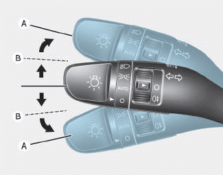
To signal a turn, push down on the lever for a left turn or up for a right turn in position (A). To signal a lane change, move the turn signal lever slightly and hold it in position (B).The lever will return to the OFF position when released or when the turn is completed.

Copyright © 2025 www.hi30.net