Hyundai i-30: Cylinder Block / Piston and Connecting Rod
Components and components location
1. Piston ring
2. Piston
3. Piston pin
4. Connecting rod
|
5. Connecting
rod upper bearing
6. Connecting rod lower bearing
7. Connecting rod bearing cap
8. Snap ring
|
Repair procedures
| •
|
Use fender covers to avoid damaging painted surfaces.
|
| •
|
To avoid damaging the cylinder head, wait until the engine coolant
temperature drops below normal temperature before removing it.
|
| •
|
When handling a metal gasket, take care not to fold the gasket
or damage the contact surface of the gasket.
|
| •
|
To avoid damage, unplug the wiring connectors carefully while
holding the connector portion.
|
|
| •
|
Mark all wiring and hoses to avoid misconnection.
|
| •
|
Turn the crankshaft pulley so that the No.1 piston is at TDC
(Top dead center).
|
|
|
1. |
Remove the engine assembly from the vehicle.
(Refer to Engine and Transaxle Assembly - "Engine and Transaxle Assembly")
|
|
2. |
Remove the transaxle assembly from the engine assembly.
(Refer to Double Clutch Transmission (DCT) System - "Double Clutch Transmission
(DCT)")
|
|
3. |
Remove the flywheel.
(Refer to Cylinder Block - "Flywheel")
|
|
4. |
Remove the rear oil seal.
(Refer to Cylinder Block - "Rear Oil Seal")
|
|
5. |
Install the engine to engine stand for disassembly.
|
|
6. |
Remove the timing chain.
(Refer to Timing System - "Timing Chain")
|
|
7. |
Remove the intake manifold.
(Refer to Intake and Exhaust System - "Intake Manifold")
|
|
8. |
Remove the exhaust manifold.
(Refer to Intake and Exhaust System - "Exhayst Manifold")
|
|
9. |
Remove the cylinder head assembly.
(Refer to Cylinder Head Assembly - "Cylinder Head")
|
|
10. |
Remove the A/C compressor.
(Refer to Heating, Ventilation Air conditioning - "Compressor")
|
|
11. |
Remove the water inlet fitting.
(Refer to Cooling System - "Water Inlet Fitting")
|
|
12. |
Remove the knock sensor.
(Refer to Engine Control / Fuel System - "Knock Sensor")
|
|
13. |
Remove the oil pan.
(Refer to Lubrication System - "Oil Pan")
|
|
14. |
Remove the ladder frame.
(Refer to Cylinder Block - "Cylinder Block")
|
|
15. |
Check the connecting rod side clearance.
|
|
16. |
Remove the connecting rod bearing caps and check oil clearance.
|
|
17. |
Remove the piston and connecting rod assemblies.
|
(1) |
Using a ridge reamer, remove all the carbon from the top of
the cylinder.
|
|
(2) |
Remove the connecting rod bearing cap (A).
|
|
(3) |
Push the piston, connecting rod assembly (B) and upper bearing
through the top of the cylinder block.
|
• |
Mark the connecting rod caps for reassembly
in the original position and direction.
|
|
|
• |
Keep the bearings, connecting rod and cap together.
|
|
• |
Arrange the piston and connecting rod assemblies
in the correct order.
|
|
• |
Mark the piston and connecting rod assemblies
for reassembly in the original position.
|
|
|
|
|
18. |
Check the piston pin will be rotated smoothly in the piston.
If the peston pin does not totate, replace the piston and piston pin
as a set.
|
|
19. |
Remove the piston rings.
|
(1) |
Using a piston ring expander, remove the 2 compression rings.
|
|
(2) |
Remove 2 side rails and the oil ring spacer by hand.
|
• |
Arrange the piston rings in the correct order
only.
|
|
• |
Do not apply excessive force when removing the
oil ring from the piston as it may break the
oil ring.
|
|
|
|
|
20. |
Remove the connecting rod from the piston.
Remove the piston pin from the piston.
|
Connecting Rod
|
1. |
Check the connecting rod side clearance.
Using a feeler gauge, measure the end play while moving the connecting
rod back and forth.
|
Standard end play :
0.10 - 0.25 mm (0.0039 - 0.0098 in)
|
| •
|
If out-of-tolerance, install a new connecting rod.
|
| •
|
If still out-of-tolerance, replace the crankshaft.
|
|
|
2. |
Check the connecting rod bearing oil clearance.
|
(1) |
Check the match marks on the connecting rod and cap are aligned
to ensure correct reassembly.
|
|
(2) |
Remove the 2 connecting rod cap bolts.
|
|
(3) |
Remove the connecting rod cap and lower bearing.
|
|
(4) |
Clean the crank pin journal and bearing.
|
|
(5) |
Place a plastigage across the crankshaft pin journal.
|
|
(6) |
Reinstall the lower bearing and cap, and tighten the bolts.
|
Tightening torque :
11.0 - 15.0 N.m (1.1 - 1.5 kgf.m, 8.0 - 10.8 lb-ft)
+ 88 - 92°
|
|
• |
Do not turn the crankshaft.
|
|
|
|
(7) |
Remove the 2 bolts, connecting rod cap and lower bearing.
|
|
(8) |
Measure the plastigage at its widest point.
|
Standard oil clearance :
0.018 - 0.036 mm (0.0007 - 0.0014 in)
|
|
|
(9) |
If the plastigage measures too wide or too narrow, remove the
upper and lower bearing and then install a new bearings with
the same color mark (Refer to connecting rod bearing selection
table) Recheck the oil clearance.
|
• |
Do not file, shim, or scrape the bearings or
the caps to adjust clearance.
|
|
|
|
(10) |
If the plastigage shows the clearance is still incorrect, try
the next lager or smaller bearing. (Refer to connecting rod
bearing selection table Recheck the oil clearance.
|
• |
If the proper clearance cannot be obtained by
using the appropriate lager or smaller bearings,
replace the crankshaft and start over.
|
|
|
• |
If the alignment marks are unreadable because
of an accumulation of grease or grime, don't
clean with a wire or abrasive cleaner. Clean
only with correct cleaning solvent or detergent.
|
|
Connecting Rod Mark Location
Discrimination of Connecting Rod
Grade
|
Mark
|
Connecting Rod Big-end Inner Diameter
|
0
|
A
|
42.000 - 42.006 mm
(1.6535 - 1.6537 in)
|
1
|
B
|
42.006 - 42.012 mm
(1.6537 - 1.6540 in)
|
2
|
C
|
42.012 - 42.018 mm
(1.6540 - 1.6542 in)
|
Crankshaft Pin Journal Mark Location
Discrimination of Crankshaft Pin Journal
Class
|
Mark
|
Crankshaft Pin Journal outer Diameter
|
I
|
1
|
38.966 - 38.972 mm
(1.5340 - 1.5343 in)
|
II
|
2
|
38.960 - 38.966 mm
(1.5338 - 1.5340 in)
|
III
|
3
|
38.954 - 38.960 mm
(1.5336 - 1.5338 in)
|
Connecting Rod Bearing Mark Location
Discrimination of Connecting Rod Bearing
Grade
|
Color
|
Connecting Rod Bearing Thickness
|
A
|
Blue
|
1.514 - 1.517 mm
(0.0596 - 0.0597 in)
|
B
|
Black
|
1.511 - 1.514 mm
(0.0595 - 0.0596 in)
|
C
|
None
|
1.508 - 1.511 mm
(0.0594 - 0.0595 in)
|
D
|
Green
|
1.505 - 1.508 mm
(0.0593 - 0.0594 in)
|
E
|
Yellow
|
1.502 - 1.505 mm
(0.0591 - 0.0593 in)
|
|
|
(11) |
Select the bearing by using selection table.
Connecting Rod Bearing Selection Table
Connecting Rod Bearing
|
Connecting Rod Mark
|
0 (A)
|
1 (B)
|
2 (C)
|
Crank shaft pin journal mark
|
I (1)
|
E (Yellow)
|
D (Green)
|
C (None)
|
II (2)
|
D (Green)
|
C (None)
|
B (Black)
|
III (3)
|
C (None)
|
B (Black)
|
A (Blue)
|
|
|
|
3. |
Check the connecting rods.
|
(1) |
When reinstalling, make sure that cylinder numbers put on the
connecting rod and cap at disassembly match. When a new connecting
rod is installed, make sure that the notches for holding the
bearing in place are on the same side.
|
|
(2) |
Replace the connecting rod if it is damaged on the thrust faces
at either end. Also if step wear or a severely rough surface
of the inside diameter of the small end is apparent, the rod
must be replaced as well.
|
|
(3) |
Using a connecting rod aligning tool, check the rod for bend
and twist. If the measured value is close to the repair limit,
correct the rod by a press. Any connecting rod that has been
severely bent or distorted should be replaced.
|
Allowable bend of connecting rod :
0.05 mm (0.0020 in.) or less for 100 mm (3.94 in.)
Allowable twist of connecting rod :
0.10 mm (0.0039 in.) or less for 100 mm (3.94 in.)
|
|
|
Piston
|
1. |
Clean the piston
|
(1) |
Using a gasket scraper, remove the carbon from the piston top.
|
|
(2) |
Using a groove cleaning tool, clean the piston ring grooves.
|
|
(3) |
Using solvent and a brush, thoroughly clean the piston.
|
• |
Do not use a wire brush.
|
|
|
|
|
2. |
Check the piston-to-cylinder clearance by calculating the difference
between the cylinder bore inner diameter and the piston outer diameter.
|
Piston-to-cylinder clearance :
0.035 - 0.055 mm (0.0014 - 0.0022 in)
|
|
(1) |
Using a cylinder bore gauge, measure the cylinder bore diameter
at position in the thrust and axial direction.
|
Cylinder bore diameter :
71.60 - 71.63 mm (2.8188 - 2.8200 in.)
|
|
|
(2) |
Measure the piston outside diameter at 35 mm (1.3780 in) from
top land of the piston.
|
Piston outside diameter :
71.555 - 71.585 mm (2.8171 - 2.8183 in)
|
|
|
|
3. |
Select the piston matching with cylinder bore class.
|
Piston-to-cylinder clearance :
0.007 - 0.043 mm (0.0009 - 0.0017 in)
|
|
(1) |
Check the cylinder bore size code on the cylinder block side
surface.
Discrimination of cylinder bore size
Grade
|
Size code
|
Cylinder Bore inner Diameter
|
a
|
A
|
71.60 - 71.61 mm
(2.8189 - 2.8193 in)
|
b
|
B
|
OVER 71.61 - TO 71.62 mm
(OVER 2.8193 - TO 2.8197 in)
|
c
|
C
|
OVER 71.62 - TO 71.63 mm
(OVER 2.8197 - TO 2.8201 in)
|
|
|
(2) |
Check the piston size code (A) and the front mark (B) on the
piston top face.
Discrimination of Piston Outer Diameter
Grade
|
Size code
|
Piston Outer Diameter
|
a
|
A
|
71.555 - 71.565 mm
(2.8171 - 2.8175 in)
|
b
|
B
|
71.565 - 71.575 mm
(2.8175 - 2.8179 in)
|
c
|
C
|
71.575 - 71.585 mm
(2.8179 - 2.8183 in)
|
|
|
Piston Rings
|
1. |
Inspect the piston ring side clearance.
Using a feeler gauge, measure the clearance between new piston ring
and the wall of the ring groove.
|
Piston ring groove width
No.1 : 1.235 - 1.250 mm (0.0486 - 0.0492 in.)
No.2 : 1.03 - 1.05 mm (0.0405 - 0.0413 in)
Oil ring : 1.995 - 2.010 mm (0.0785 - 0.0791 in)
Piston ring side clearance
No.1 : 0.05 - 0.08 mm (0.0020 - 0.0031 in)
No.2 : 0.04 - 0.08 mm (0.0015 - 0.0031 in)
Oil ring : 0.040 - 0.085 mm (0.0016 - 0.0033 in)
|
If the clearance is greater than maximum, replace the piston.
|
|
2. |
Inspect piston ring end gap.
To measure the piston ring end gap, insert a piston ring into the cylinder
bore. Position the ring at right angles to the cylinder wall by gently
pressing it down with a piston. Measure the gap with a feeler gauge.
If the gap exceeds the service limit, replace the piston ring. If the
gap is too large, recheck the cylinder bore diameter against the wear
limits. If the bore is over the service limit, the cylinder block must
be replaced.
|
Piston ring end gap
No.1 : 0.13 - 0.18 mm (0.0051 - 0.0071 in)
No.2 : 0.25 - 0.35 mm (0.0098 - 0.0137 in)
Oil ring : 0.10 - 0.40 mm (0.0039 - 0.0157 in)
|
|
Piston Pins
|
1. |
Measure the diameter of the piston pin.
|
Piston pin outer diameter :
17.997 - 18.000 mm (0.7085 - 0.7086 in)
|
|
|
2. |
Measure the piston pin-to-piston clearance.
|
Piston pin-to-piston clearance :
0.007 - 0.014 mm (0.00027 - 0.00055 in.)
|
|
|
3. |
Check the difference between the piston pin outer diameter and the connecting
rod small end inner diameter.
|
Piston pin-to-connecting rod interference :
0.005 - 0.014 mm (0.0002 - 0.0006 in)
|
|
| •
|
Thoroughly clean all parts to be assembled.
|
| •
|
Before installing the parts, apply fresh engine oil to all sliding
and rotating surfaces.
|
| •
|
Replace all gaskets, O-rings and oil seals with new parts.
|
|
|
1. |
Assemble the piston and connecting rod.
|
(1) |
The piston front mark (A) and the connecting rod front mark
(B) must face the timing chain side of the engine.
|
|
|
2. |
Install the piston rings.
|
(1) |
Install the oil ring expander and 2 side rails by hand with
the code mark facing upward.
|
|
(2) |
Using a piston ring expender, install the 2 compression rings
with the code mark facing upward.
|
|
(3) |
Position the piston rings so that the ring ends are as shown.
|
|
|
3. |
Install the connecting rod bearings.
|
(1) |
Align the bearing claw with the groove of the connecting rod
and connecting rod cap.
|
|
(2) |
Install the bearings (A) in the connecting rod and connecting
rod cap (B).
|
• |
Be careful not to change the position of bearing
caps.
|
|
|
|
|
4. |
Install the piston and connecting rod assemblies.
|
• |
Before installing the pistons, apply a coat of engine
oil to the ring grooves and cylinder bores.
|
|
• |
The piston front mark (A) and the connecting rod front
mark (B) must face the timing chain side of the engine.
|
|
|
(1) |
Install the ring compressor, check that the bearing is securely
in place, then position the piston in the cylinder, and tap
it in using the wooden handle of a hammer.
|
|
(2) |
Stop after the ring compressor pops free, and check the connecting
rod to check journal alignment before pushing the piston into
place.
|
|
(3) |
Install the rod caps with bearings, and tighten the bolts.
|
Tightening torque :
11.0 - 15.0 N.m (1.1 - 1.5 kgf.m, 8.0 - 10.8 lb-ft)
+ 88 - 92°
|
|
• |
Using the SST (09221-4A000), tighten the bolts
which need to be tightened with the angular
tightening method.
|
|
|
• |
Do not reuse the connecting rod cap bolts.
|
|
• |
Maintain downward force on the ring compressor
to prevent the rings from expending before entering
the cylinder bore.
|
|
|
|
|
5. |
Check the connecting rod end play.
|
|
6. |
Assemble the other parts in the reverse order of disassembly.
|
Repair procedures
Removal
1.
Remove the dual clutch transmission assembly.
(Refer to Double Clutch Transmission (DCT) System - "Double Clutch Transmission
(DCT)")
2...
Components and components location
Components
1. Thrust bearing
2. Upper main bearing
3. Crankshaft
4. Lower main
bearing
5...
Other information:
..
If your temperature gauge indicates
overheating, you experience a loss
of power, or hear loud pinging or
knocking, the engine may be overheating.
If this happens, you should:
1. Pull off the road and stop as soon
as it is safe to do so.
2...
Categories
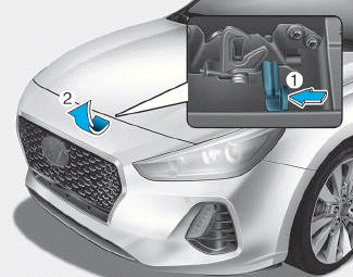
Opening the bonnet
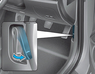
1. Park the vehicle and set the parking
brake.
2. Pull the release lever to unlatch
the bonnet. The bonnet should
pop open slightly.
read more


 Rear Oil Seal
 Crankshaft