Hyundai i-30: Cylinder Block / Crankshaft
Components and components location
1. Thrust bearing
2. Upper main bearing
3. Crankshaft
|
4. Lower main
bearing
5. Main bearing cap
|
Repair procedures
| •
|
Use fender covers to avoid damaging painted surfaces.
|
| •
|
To avoid damaging the cylinder head, wait until the engine coolant
temperature drops below normal temperature before removing it.
|
| •
|
When handling a metal gasket, take care not to fold the gasket
or damage the contact surface of the gasket.
|
| •
|
To avoid damage, unplug the wiring connectors carefully while
holding the connector portion.
|
|
| •
|
Mark all wiring and hoses to avoid misconnection.
|
| •
|
Turn the crankshaft pulley so that the No.1 piston is at TDC
(Top dead center).
|
|
|
1. |
Remove the engine assembly from the vehicle.
(Refer to Engine and Transaxle Assembly - "Engine and Transaxle Assembly")
|
|
2. |
Remove the transaxle assembly from the engine assembly.
(Refer to Double Clutch Transmission (DCT) System - "Double Clutch Transmission
(DCT)")
|
|
3. |
Remove the flywheel.
(Refer to Cylinder Block - "Flywheel")
|
|
4. |
Remove the rear oil seal.
(Refer to Cylinder Block - "Rear Oil Seal")
|
|
5. |
Install the engine to engine stand for disassembly.
|
|
6. |
Remove the timing chain.
(Refer to Timing System - "Timing Chain")
|
|
7. |
Remove the intake manifold.
(Refer to Intake and Exhaust System - "Intake Manifold")
|
|
8. |
Remove the exhaust manifold.
(Refer to Intake and Exhaust System - "Exhayst Manifold")
|
|
9. |
Remove the cylinder head assembly.
(Refer to Cylinder Head Assembly - "Cylinder Head")
|
|
10. |
Remove the A/C compressor.
(Refer to Heating, Ventilation Air conditioning - "Compressor")
|
|
11. |
Remove the inlet fitting.
(Refer to Cooling System - "Inlet Fitting")
|
|
12. |
Remove the knock sensor.
(Refer to Engine Control / Fuel System - "Knock Sensor")
|
|
13. |
Remove the oil pump.
(Refer to Lubrication System - "Oil Pump")s
|
|
14. |
Remove the ladder frame.
(Refer to Cylinder Block - "Cylinder Block")
|
|
15. |
Remove the piston and connecting rod assemblies.
(Refer to Cylinder Block - "Piston and Connecting Rod")
|
|
16. |
Remove the main bearing caps and check oil clearance.
|
|
17. |
Check the crankshaft end play.
|
|
18. |
Lift the crankshaft (A) out of engine, being careful not to damage journals.
|
• |
Arrange the main bearings and thrust bearings in the
correct order.
|
|
|
|
1. |
Check the crankshaft bearing oil clearance.
|
(1) |
To check main bearing-to-journal oil clearance, remove the main
bearings.
|
|
(2) |
Clean each main journal and bearing half with a clean shop tower.
|
|
(3) |
Place one strip of plastigage across each main journal.
|
|
(4) |
Use the SST (09221-4A000), reinstall the bearings and bolts
as following method with specified torque. In the sequence.
|
Tightening torque :
17.7 - 21.6 N.m (1.8 - 2.2 kgf.m, 13.0 - 15.9 lb-ft)
+ 108 - 112°
|
|
• |
Do not turn the crankshaft.
|
|
• |
Always use new main bearing cap bolts.
|
|
|
|
(5) |
Remove the cap and bearing again, and measure the widest part
of the plastigage.
|
Standard oil clearance :
No. 1,2,4,5 journal : 0.012 - 0.030 mm (0.0005 - 0.0012
in.)
No. 3 journal : 0.018 - 0.036 mm (0.0007 - 0.0014 in.)
|
|
|
(6) |
If the plastigage measures too wide or too narrow, remove the
upper half of the bearing, install a new, complete bearing with
the same color mark (select the color as shown in the next column),
and recheck the clearance.
|
• |
Do not file, shim, or scrape the bearings or
the caps to adjust clearance.
|
|
|
|
(7) |
If the plastigage shows the clearance is still incorrect, try
the next larger or smaller bearing (the color listed above or
below that one), and check clearance again.
|
• |
If the proper clearance cannot be obtained by
using the appropriate larger or smaller bearings,
replace the crankshaft and start over.
|
|
|
• |
If the marks are indecipherable because of an
accumulation of dirt and dust, do not scrub
them with a wire brush or scraper. Clean them
only with solvent or detergent.
|
|
Cylinder block crankshaft journal bore mark location
Letters have been stamped on the block as a mark for the size
of each of the 5 main journal bores.
Use them, and the numbers or bar stamped on the crank (marks
for main journal size), to choose the correct bearings.
Grade
|
Mark
|
Cylinder Block Crankshaft journal Bore Inner Diameter
|
a
|
A
|
52.000 - 52.006 mm
(2.0472 - 2.0475 in)
|
b
|
B
|
OVER 52.006 - TO 52.012 mm
(OVER 2.0475 - TO 2.0477 in)
|
c
|
C
|
OVER 52.012 - TO 52.018 mm
(OVER 2.0477 - TO 2.0480 in)
|
Crankshaft Main Journal Mark Location
Discrimination of Crankshaft Main Journal
Class
|
Mark
|
Crankshaft main journalouter diameter
|
I
|
1
|
47.954 - 47.960 mm
(1.8879 - 1.8881 in)
|
II
|
2
|
47.948 - 47.954 mm
(1.8877 - 1.8879 in)
|
III
|
3
|
47.942 - 47.948 mm
(1.8874 - 1.8877 in)
|
Crankshaft Main Bearing Mark Location
Mark
|
Color
|
Crankshaft Main Bearing Thickness
|
1
|
Blue
|
2.023 - 2.026 mm(0.0796 - 0.0797 in)
|
2
|
Black
|
2.020 - 2.023 mm(0.0795 - 0.0796 in)
|
3
|
None
|
2.017 - 2.020 mm(0.0794 - 0.0795 in)
|
4
|
Green
|
2.014 - 2.017 mm(0.0792 - 0.0794 in)
|
5
|
Yellow
|
2.011 - 2.014 mm(0.0791 - 0.0792 in)
|
6
|
Red
|
2.008 - 2.011 mm (0.0790 - 0.0791 in)
|
|
|
(8) |
Select the bearing by using selection table.
Crankshaft Main Bearing Selection Table
No. 1,2,4,5 journal
Crankshaft Main Bearing
|
Cylinder Block Crankshaft Journal Bore Mark
|
a (A)
|
b (B)
|
c (C)
|
Crank shaft main journal mark
|
I (1)
|
5 (Yellow)
|
4 : GREEN
|
3 : NONE
|
II (2)
|
4 : GREEN
|
3 : NONE
|
2 : BLOCK
|
III (3)
|
3 : NONE
|
2 : BLOCK
|
1 : BLUE
|
No. 3 journal
Crankshaft Main Bearing
|
Cylinder Block Crankshaft Journal Bore Mark
|
a (A)
|
b (B)
|
c (C)
|
Crank shaft main journal mark
|
I (1)
|
6 (RED)
|
5 (Yellow)
|
4 : GREEN
|
II (2)
|
5 (Yellow)
|
4 : GREEN
|
3 : NONE
|
III (3)
|
4 : GREEN
|
3 : NONE
|
2 : BLOCK
|
|
|
|
2. |
Check crankshaft end play.
Using a dial indicator, measure the thrust clearance while prying the
crankshaft back and forth with a screwdriver.
|
Standard end play :
0.10 - 0.28 mm ( 0.0039 - 0.0110 in)
|
If the end play is greater than maximum, replace the center bearings
as a set.
|
|
3. |
Inspect the crankshaft main journals and pin journals.
Using a micrometer, measure the diameter of each main journal and pin
journal.
|
Main journal diameter :
47.942 - 47.960 mm (1.8874 - 1.8881 in)
Pin journal diameter :
38.954 - 38.972 mm (1.5336 - 1.5343 in)
|
|
| •
|
Thoroughly clean all parts to be assembled.
|
| •
|
Before installing the parts, apply fresh engine oil to all sliding
and rotating surfaces.
|
|
|
1. |
Install the crankshaft main bearings.
|
• |
Upper bearings have an oil groove of oil holes; Lower
bearings do not.
|
|
|
(1) |
Align the bearing claw with the claw groove of the cylinder
block, push in the 5 upper bearings (A).
|
|
(2) |
Install the thrust bearings.
Install the 2 thrust bearings (A) under the No.3 journal position
of the cylinder block with the oil grooves facing outward.
|
|
(3) |
Install the crankshaft lower main bearing.
Align the bearing claw with the groove of the crankshaft lower
bearing and crankshaft main bearing cap.
|
|
|
2. |
Place the crankshaft (A) on the cylinder block.
|
|
3. |
Install the main bearing caps.
|
• |
Always use new main bearing cap bolts.
|
|
• |
If any of the bearing cap bolts are broken or deformed,
replace it.
|
|
|
(1) |
Apply a light coat of engine oil on the threads and under the
bearing cap bolts.
|
|
(2) |
Install and uniformly tighten the 10 bearing cap bolts, in several
passes, in the sequence shown.
|
Tightening torque :
17.7 - 21.6 N.m (1.8 - 2.2 kgf.m, 13.0 - 15.9 lb-ft)
+ 108 - 112°
|
|
• |
Using the SST (09221-4A000), tighten the bolts
which need to be tightened with the angular
tightening method.
|
|
|
• |
Do not reuse the main bearing cap bolts.
|
|
|
|
(3) |
Check that the crankshaft turns smoothly.
|
|
|
4. |
Check the crankshaft end play.
|
|
5. |
Assemble the other parts in the reverse order of disassembly.
|
In case the crankshaft is replaced with a new one, select the
proper connecting rod bearing according to the pin journal mark
on the crankshaft.
|
• |
Connecting rod bearing selection.
(Refer to Cylinder Block Assembly - "Piston and Connecting
Rod")
|
|
|
Components and components location
Components
1. Piston ring
2. Piston
3. Piston pin
4. Connecting rod
5...
Repair procedures
Disassembly
•
Use fender covers to avoid damaging painted surfaces...
Other information:
Repair procedures
Replacement
•
Put on gloves to prevent hand injuries.
•
When removing with a flat-tip screwdriver or remover, wrap protective
tape around the tools to prevent damage to components...
The sensitivity of vehicle speed
when following the front vehicle to
maintain the set distance can be
adjusted. Go to the 'User Settings →
Driving Assist → Smart Cruise
Control Speed → Slow/Normal/ Fast'
on the LCD display. You may select
one of the three stages you prefer...
Categories
Operating door locks from
outside the vehicle
Mechanical key
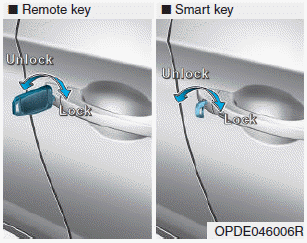
Turn the key toward the rear of the
vehicle to unlock and toward the front
of the vehicle to lock.
If you lock/unlock the driver's door
with a key, a driver’s door will
lock/unlock automatically.
read more


 Piston and Connecting Rod
 Cylinder Block