Hyundai i30 (PD): Blind-spot collision warning (BCW) system / RCCW (Rear Cross-Traffic Collision Warning)
The Rear Cross-Traffic Collision warning function monitors approaching cross traffic from the left and right side of the vehicle when your vehicle is in reverse.
Operating conditions
To operate:
Go to the 'User Settings → Driver Assistance and select Rear Cross- Traffic Collision warning' on the LCD display.
The system will turn on and standby to activate. If you deactivate this function in the cluster, the system will stop.
Refer to "User settings mode" in chapter 3 for more details.
Information
If the vehicle is turned off then on again, the BCW system returns to the previous state.
The system will activate when vehicle speed is below 6.2 mph (10 km/h) and with the shift lever in R (Reverse).
The Rear Cross-Traffic Collision warning detecting range is approximately 0.5 m ~ 20 m (1 ft ~ 65 ft) in the direction of both lateral sides of the vehicle. An approaching vehicle will be detected if their vehicle speed is within 2.5 ~ 22.5 mph (4 km/h ~ 36 km/h).
Note that the detecting range may vary under certain conditions. As always, use caution and pay close attention to your surroundings when reversing up your vehicle.
Warning type
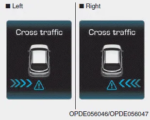
If the vehicle detected by the sensors approaches your vehicle, the warning chime will sound, the warning light on the outside rearview mirror will blink and a message will appear on the LCD display.
Information
- The warning chime will turn off
when:
- The detected vehicle moves out of the sensing area or
- When the vehicle is right behind your vehicle or
- When the vehicle is not approaching your vehicle or
- When the other vehicle slows down. - The system may not operate properly due to other factors or circumstances. Always pay attention to your surroundings.
- If the sensing area near the rear bumper is blocked by either a wall or barrier or by a parked vehicle, the system sensing area may be reduced.
WARNING
- When BCW is activated, the warning light on the outside rearview mirror will illuminate whenever a vehicle is detected at the rear side by the system. To avoid accidents, do not focus only on the warning light and neglect to see the surrounding of the vehicle.
- Drive safely even though the vehicle is equipped with a Blind-spot Collision Warning (BCW) system and Rear Cross-Traffic Collision Warning (RCCW). Do not solely rely on the system but check your surrounding before changing lanes or backing the vehicle up. The system may not alert the driver in some conditions so always check your surroundings whilst driving.
- The Blind-spot Collision Warning (BCW) system and Rear Cross-Traffic Collision warning (RCCW) are not a substitute for proper and safe driving practices. Always drive safely and use caution when changing lanes or reversing your vehicle. The Blind-spot Collision Warning (BCW) system may not detect every object alongside the vehicle.
NOTICE
- The system may not work properly when the bumper has been damaged, or if the rear bumper has been replaced or repaired.
- The sensing range differs somewhat according to the width of the road. When the road is narrow, the system may detect other vehicles in the next lane OR when the road is wide, the system may not detect other vehicles in the next lane.
- The system may turn off due to strong electromagnetic waves.
Operating conditions To operate: Press the BCW switch with the Ignition switch in the ON position. The indicator on the BCW switch will illuminate.
The sensors are located inside the rear bumper. Always keep the rear bumper clean for proper operation of the system. Warning message BCW (Blind-Spot Collision Warning) system disabled.
Other information:
Hyundai i30 (PD) 2018-2024 Owner's Manual: Smart Cruise Control speed
To set Smart Cruise Control speed 1. Push the button on the steering wheel to turn the system on. The cruise () indicator will illuminate. 2. Accelerate to the desired speed. The Smart Cruise Control speed can be set as follows: 20 mph (30 km/h)~110 mph (180 km/h) : when there is no vehicle in front 0 mph (0 km/h)~110
Hyundai i30 (PD) 2018-2024 Owner's Manual: Vehicle weight
Two labels on your driver’s door sill show how much weight your vehicle was designed to carry: the Tyre and Loading Information Label and the Certification Label. Before loading your vehicle, familiarize yourself with the following terms for determining your vehicle's weight ratings, from the vehicle's specifications and the Cert
Categories
- Manuals Home
- Hyundai i30 Owners Manual
- Light bulbs
- Specifications & Consumer information
- Explanation of scheduled maintenance items
- New on site
- Most important about car
