Hyundai i-30: Timing System / Timing Chain Cover
Hyundai i30 (PD) 2018-2025 Service Manual / Engine Mechanical System / Timing System / Timing Chain Cover
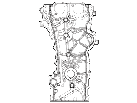
Components and components location
| Components |
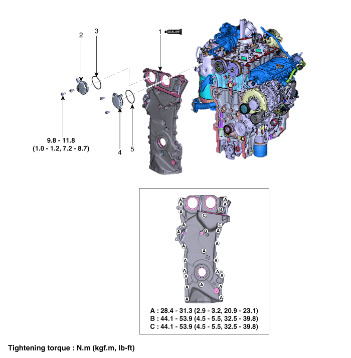
| 1. Timing chain
cover 2. Exhaust Oil control solenoide (OCS) 3. Exhaust Oil control solenoide (OCS) O-ring |
4. Intake Oil
control solenoide (OCS) 5. Intakd Oil control solenoide (OCS) O-ring |
Repair procedures
| Removal |
Engine removal is not required for this procedure.
|

|

| 1. |
Disconnect the battery negative terminal.
|
| 2. |
Remove the RH front wheel.
(Refer to Suspension System - "Wheel")
|
| 3. |
Remove the engine room under cover.
(Refer to Engine and Transaxle Assembly - "Engine Room Under Cover")
|
| 4. |
Remove the engine cover.
(Refer to Engine and Transaxle Assembly - "Engine Cover")
|
| 5. |
Remove the drive belt.
(Refer to Timing System - "Drive Belt")
|
| 6. |
Remove the water pump pulley and then remove the water pump.
(Refer to Cooling System - "Water Pump")
|
| 7. |
Remove the idler.
(Refer to Timing System - "Idler")
|
| 8. |
Remove the drive belt tensioner.
(Refer to Timing System - "Drive Belt Tensioner")
|
| 9. |
Remove the crankshaft damper pulley.
(Refer to Timing System – "Crankshaft Damper Pulley")
|
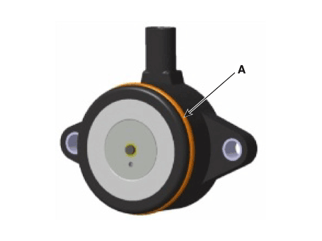
| 10. |
Remove the intake oil control solenoide (OCS) (A), exhaust oil control
solenoide (OCS) (B).
|
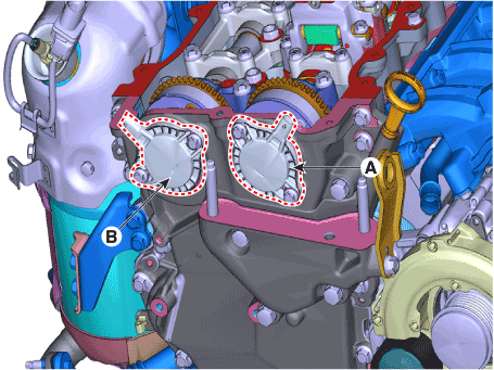
| 11. |
Remove the cylinder head cover.
(Refer to Cylinder Head Assembly - "Cylinder Head Cover")
|
| 12. |
Remove the engine mounting support bracket.
(Refer to Engine and Transaxle Assembly - "Engine Mounting")
|
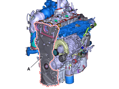
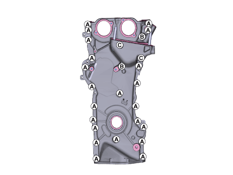
| 13. |
Remove the timing chain cover (A) by gently prying the gaps between
the cylinder head and cylinder block.
|
| Installation |
| 1. |
Install the timing chain cover (A).
|
| 2. |
Replace the front oil seal if necessary.
(Refer to Timing System - "Front Oil Seal")
|
| 3. |
Install the engine mounting support bracket.
(Refer to Engine and Transaxle Assembly - "Engine Mounting")
|
| 4. |
Install the cylinder head cover.
(Refer to Cylinder Head Assembly - "Cylinder Head Cover")
|
| 5. |
Install the intake oil control solenoide (OCS) (A), exhaust oil control
solenoide (OCS) (B).
|
| 6. |
Install the other parts in the reverse order of removal.
|
 Front Oil Seal
Repair procedures
Removal and Installation
1.
Remove the crankshaft damper pulley.
(Refer to Timing System - "Crankshaft Damper Pulley")
2...
 Timing Chain
Components and components location
Components
1. Timing chain
2. Timing chain cam guide
3. Timing chain guide
4...
Other information:
Hyundai i30 (PD) 2018-2025 Owner's Manual: Engine compartment
■ Petrol Engine (Kappa 1.0 T-GDI) ■ Petrol Engine (Kappa 1.4 T-GDI) 1. Engine coolant reservoir/Engine coolant cap 2. Brake/clutch fluid reservoir 3. Air cleaner 4. Engine oil dipstick 5. Engine oil filler cap 6. Windscreen washer fluid reservoir 7...
Hyundai i30 (PD) 2018-2025 Service Manual: Repair procedures
Inspection Check it by the procedure below to see if the function of the ECM is normal. 1. Turn the ignition key to the "ON" position. 2. Cover the forward facing sensor...
Categories
- Manuals Home
- 3rd Generation i30 Owners Manual
- 3rd Generation i30 Service Manual
- Front windscreen wiper service position
- Shift-lock system. Shift-lock release
- Engine compartment
- New on site
- Most important about car
Gauges and meters
Speedometer
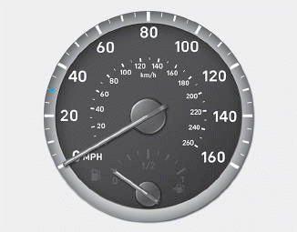
The speedometer indicates the speed of the vehicle and is calibrated in kilometers per hour (km/h) and/or miles per hour (MPH).
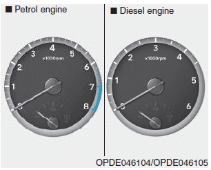
Tachometer

Copyright © 2025 www.hi30.net