Hyundai i-30: Rear Suspension System / Rear Assist Arm
Hyundai i30 (PD) 2018-2025 Service Manual / Suspension System (NON-ECS) / Rear Suspension System / Rear Assist Arm
Repair procedures
| Removal |
| 1. |
Loosen the wheel nuts slightly.
Raise the vehicle, and make sure it is securelysupported.
|
| 2. |
Remove the rear wheel and tire (A) from the raerhub.
|

| 3. |
Loosen the bolt and then remove the assist arm fromthe rear carrier.
|
| 4. |
Loosen the bolt & nut and then remove the rearassist arm (A) with the
rear cross member.
|
| 5. |
Installation in the reverse of removal.
|
| 6. |
Check the alignment.
(Refer to Tires/Wheels - "Alignment")
|
| Inspection |
| 1. |
Check the bushing for wear and deterioration.
|
| 2. |
Check the rear assist arm for deformation..
|
| 3. |
Check for all bolts and nut.
|
 Rear Stabilizer Bar
Repair procedures
Removal
1.
Loosen the wheel nuts slightly.
Raise the vehicle, and make sure it is securelysupported...
 Trailing Arm
Repair procedures
Removal
1.
Loosen the wheel nuts slightly.
Raise the vehicle, and make sure it is securelysupported...
Other information:
Hyundai i30 (PD) 2018-2025 Owner's Manual: Emergency Stop Signal (ESS)
The Emergency Stop Signal system alerts the driver behind by blinking the stop lights, whilst sharply and severely braking. The system is activated when: The vehicle suddenly stops. (The deceleration power exceeds 7 m/s2, and the driving speed exceeds 34 mph (55 km/h)...
Hyundai i30 (PD) 2018-2025 Service Manual: Instrument Cluster
Components and components location Components TFT LCD Cluster (Standard) TFT LCD Cluster (7Inch) Connector Pin Information Connector Pin Information No. Description No. Description 1 Ground 21 Trip switch (-) 2 Illumination (-) 22 Trip switch 1 (+) 3 Rheostat switch (Down)_Input 23 Trip switch 2 (+) 4 Rheostat switch (Up)_Input 24 M/T N switch 5 Dentent 25 Driver mode switch 6 P 26 - 7 R 27 - 8 N 28 Low washer level sensor 9 D 29 M-CAN (Low) 10 S 30 M-CAN (High) 11 Immobillizer 31 - 12 Vehicle speed_Output 32 C-CAN (High) 13 Alternator_Input 33 C-CAN(Low) 14 Fuel sender (+)_Input 34 - 15 - 35 - 16 Fuel sender (-)_Input 36 - 17 Water separator (+) 37 Ground 18 Airbag (+)_Input 38 - 19 Oil press switch (-)_Input 39 IGN 1 20 Tail_input 40 Battery (+) Schematic diagrams Circuit Diagram TFT LCD Cluster (Standard) TFT LCD Cluster (7Inch) Description and operation Description Communication Network Diagram Abbreviation Expalnation ECM Engine Control Module TCU Transmission Control Unit MDPS Motor Driven Power Steering AEB Autonomous Emergency Braking LKAS Lane Keeping Assist System FPS Fuel Pump Control module RR CAMERA Rear View Carmera VACUUM Vacuum Pump CLUSTER Cluster Module ACU Airbag Control Unit DATC Dual Automatic Temp Control MTC Temp Control OCS Occupant Classification System VDC Vehicle Dynamic Control BSD Blind Spot Detection AMP Amplifier AVN Head Unit (Audio / AVN) SMK Smart Key Unit WPC Wireless Power Charger IMS Integrated Memory System DDM Driver Door Module ADM Assist Door Module BCM Body Control Module B-CAN Body Controller Area Network P-CAN Powertrain Controller Area Network M-CAN Multi media Controller Area Network C-CAN Chassis Controller Area Network Cluster Variant Coding As we have more options (ESC, MDPS etc...
Categories
- Manuals Home
- 3rd Generation i30 Owners Manual
- 3rd Generation i30 Service Manual
- Engine compartment
- Exhaust System (DPF) Warning Light. Glow Indicator Light
- Light bulbs
- New on site
- Most important about car
Air bag - supplemental restraint system
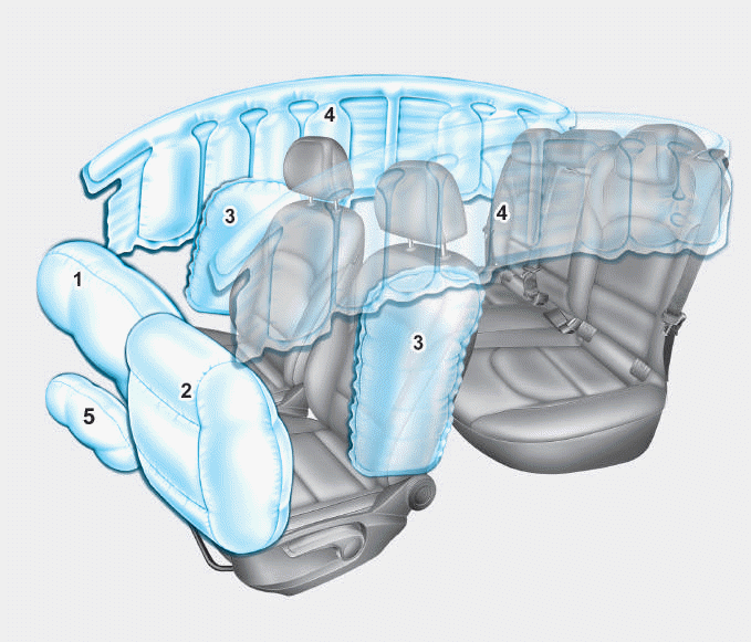
1. Driver’s front air bag
2. Passenger’s front air bag
3. Side air bag*
4. Curtain air bag*
5. Knee air bag*
6. Front passenger air bag ON/OFF
switch

Copyright © 2025 www.hi30.net