Hyundai i-30: Suspension System (NON-ECS) / Rear Suspension System
Hyundai i30 (PD) 2018-2025 Service Manual / Suspension System (NON-ECS) / Rear Suspension System
- Components and components location
- Rear Shock Absorber
- Rear Upper Arm
- Rear Lower Arm
- Rear Stabilizer Bar
- Rear Assist Arm
- Trailing Arm
- Rear Coil Spring
- Rear Cross Member
 Sub Frame
Repair procedures
Removal
1.
Loosen the wheel nuts slightly.
Raise the vehicle, and make sure it is securelysupported...
 Components and components location
Components Location
1. Rear upper
arm
2. Assist arm
3. Rear cross member
4. Rear stabilizer bar
5. Trailing arm
6...
Other information:
Hyundai i30 (PD) 2018-2025 Owner's Manual: Engine compartment
1. Engine coolant reservoir/ Engine coolant cap 2.Brake/clutch fluid reservoir 3. Air cleaner 4. Engine oil dipstick 5. Engine oil filler cap 6.Windscreen washer fluid reservoir 7.Fuse box 8. Battery 1. Engine coolant reservoir 2...
Hyundai i30 (PD) 2018-2025 Service Manual: DCT (Dual Clutch Transmission)
Components and components location Components 1. DCT (Dual Clutch Transmission) assembly 2. DCT support bracket 3. Roll rod support bracket Repair procedures Removal 1...
Categories
- Manuals Home
- 3rd Generation i30 Owners Manual
- 3rd Generation i30 Service Manual
- Cruise control
- Light bulbs
- LKA system operation
- New on site
- Most important about car
Gauges and meters
Speedometer
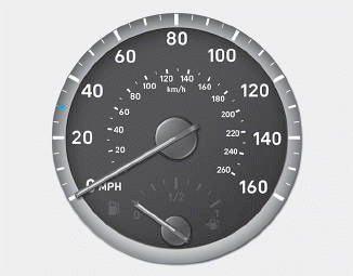
The speedometer indicates the speed of the vehicle and is calibrated in kilometers per hour (km/h) and/or miles per hour (MPH).
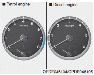
Tachometer

Copyright © 2025 www.hi30.net