Hyundai i-30: Fuses And Relays / Relay Box (Passenger Compartment)
Hyundai i30 (PD) 2018-2025 Service Manual / Body Electrical System / Fuses And Relays / Relay Box (Passenger Compartment)
Components and components location
| Component Location |
[Interior Junction Block]
| IGPM(Integrated Gateway & Power Control Module) |
| Circuit (IGPM) |
Description and operation
| Description |
Communication Network Diagram
|
Abbreviation |
Expalnation |
|
ECM |
Engine Control Module |
|
TCU |
Transmission Control Unit |
|
MDPS |
Motor Driven Power Steering |
|
AEB |
Autonomous Emergency Braking |
|
LKAS |
Lane Keeping Assist System |
|
FPS |
Fuel Pump Control module |
|
RR CAMERA |
Rear View Carmera |
|
VACUUM |
Vacuum Pump |
|
CLUSTER |
Cluster Module |
|
ACU |
Airbag Control Unit |
|
DATC |
Dual Automatic Temp Control |
|
MTC |
Temp Control |
|
OCS |
Occupant Classification System |
|
VDC |
Vehicle Dynamic Control |
|
BSD |
Blind Spot Detection |
|
AMP |
Amplifier |
|
AVN |
Head Unit (Audio / AVN) |
|
SMK |
Smart Key Unit |
|
WPC |
Wireless Power Charger |
|
IMS |
Integrated Memory System |
|
DDM |
Driver Door Module |
|
ADM |
Assist Door Module |
|
BCM |
Body Control Module |
|
B-CAN |
Body Controller Area Network |
|
P-CAN |
Powertrain Controller Area Network |
|
M-CAN |
Multi media Controller Area Network |
|
C-CAN |
Chassis Controller Area Network |
Integrated Gateway & Power control Module (IGPM)
Integrated Gateway & Power control Module (IGPM) is a module that performs the
function of conventional Junction Block and some functions of BCM.
It controls various components including lamps by using CAN communication and
IPS (replacing the function of fuse and relay) or ARISU.
IPS stands for Intelligent Power Switch, which uses the semiconductor technology
to replace the current role of fuse and relay. (The IPS chip has two functions:
1) the high current-based component control; 2) component protection from overcurrent.)
The advantages of IPS are as follows:
|

IGPM control entry
| 1. |
Switch signal input
|
| 2. |
IGPM protection
|
| 3. |
IGPM fail safe function
|
| 4. |
Auto Cut System of Dark Current
|
Repair procedures
| Fuse Inspection |
| 1. |
Check that the fuse holders are loosely held and that the fuses are
securely fixed by the holders.
|
| 2. |
Check that each fuse circuit has the exact fuse capacity.
|
| 3. |
Check the fuses for any damage.
|
Diagnosis with GDS
| 1. |
In the body electrical system, failure can be quickly diagnosed by using
the vehicle diagnostic system (GDS).
The diagnostic system (GDS) provides the following information.
|
| 2. |
Select the 'Car model' and the 'Smart Junction Block (SJB)' to be checked
in order to check the vehicle with the tester.
|
| 3. |
Select the 'Current Data' menu to search the current state of the input/output
data.
|
| 4. |
To forcibly actuate the input value of the module to be checked, select
option 'Actuation Test'
|
| 5. |
If you want to change user option, select "user option".
|
| Removal |
| 1. |
Disconnect the negative (-) battery terminal.
|
| 2. |
Remove the crash pad lower panel.
(Refer to Body - "Crash Pad Lower Panel")
|
| 3. |
Disconnect the connectors (A) from the fuse side of the SJB.
|
| 4. |
Remove the SJB (A) after loosening the mounting nuts.
|
| 5. |
Disconnect the connectors from the back side of the SJB.
|
| Installation |
| 1. |
Install the integrated gateway & power control module (SJB).
|
| 2. |
Install the crash pad lower panel.
|
| 3. |
Connect the negative (-) battery terminal.
|
| 4. |
Check that all system operates normally.
|
 Relay Box (Engine Compartment)
Components and components location
Component Location
[Engine room junction block]
E/R Junction Block
Circuit (E/R Junction Block)
[Metal Core Block (PCB)]
PCB Block
Circuit (PCB Block)
Repair procedures
Inspection
1...
 ICM (Integrated Circuit Module) Relay Box
Description and operation
Description
The ICM relay is united with (rear wiper relay, seat heater relay(front/rear),
head lamp washer relay and rear A/C relay) which installed inside the lower
crash pad...
Other information:
Hyundai i30 (PD) 2018-2025 Service Manual: Repair procedures
Inspection Steering Wheel Play Inspection 1. Turn the steering wheel so that the front wheels can face straight ahead. 2. Measure the distance the steering wheel can be turned without moving the front wheels...
Hyundai i30 (PD) 2018-2025 Service Manual: Schematic diagrams
Schematic Diagrams [Without EPB] [With EPB] Terminal Function [EPB None Apply] PIN No Desciption Current max min 1 Voltage supply for pump motor 40A 10 MΩ 2 - 1...
Categories
- Manuals Home
- 3rd Generation i30 Owners Manual
- 3rd Generation i30 Service Manual
- Light bulbs
- Front windscreen wiper service position
- Drive mode integrated control system
- New on site
- Most important about car
Gauges and meters
Speedometer
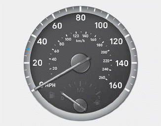
The speedometer indicates the speed of the vehicle and is calibrated in kilometers per hour (km/h) and/or miles per hour (MPH).
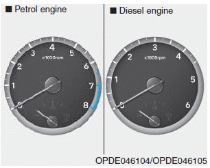
Tachometer

Copyright © 2025 www.hi30.net