Hyundai i-30: Fuses And Relays / Relay Box (Engine Compartment)
Hyundai i30 (PD) 2018-2025 Service Manual / Body Electrical System / Fuses And Relays / Relay Box (Engine Compartment)
Components and components location
| Component Location |
[Engine room junction block]
| E/R Junction Block |
| Circuit (E/R Junction Block) |
[Metal Core Block (PCB)]
| PCB Block |
| Circuit (PCB Block) |
Repair procedures
| Inspection |
| 1. |
Disconnect the negative (-) battery terminal.
|
| 2. |
Pull out the relay from the engine compartment relay block.
|
Power Relay (Type A)
Check for continuity between the terminals.
| 1. |
After supplying power to between No. 85 and 86 power relay terminals,
check that there is continuity between No. 30 and 87 terminals.
|
| 2. |
After disconnecting power between No. 85 and 86 power relay terminals,
check that there is no continuity between No. 30 and 87 terminals.
Engine Room Relay Block
|
Power Relay (Type B)
Check for continuity between the terminals.
| 1. |
After supplying power to between No. 85 and 86 power relay terminals,
check that there is continuity between No. 30 and 87 terminals.
|
| 2. |
After disconnecting power between No. 85 and 86 power relay terminals,
check that there is no continuity between No. 30 and 87 terminals.
|
Metal Core PCB block
| 1. |
Disconnect the negative (-) battery terminal.
|
| 2. |
Remove the multi fuse.
|
| 3. |
Push the four hooks (B) in the direction of the arrow and lift up the
metal core PCB block (A).
|
| 4. |
Remove the metal care PCB block by disconnet the connector.
|
Fuse
| 1. |
Check that the fuse holders are loosely held and that the fuses are
securely fixed by the holders.
|
| 2. |
Check that each fuse circuit has the exact fuse capacity.
|
| 3. |
Check the fuses for any damage.
|

Multi Fuse
Engine room fuse is to optimize the package.
|

 Components and components location
Component Location
[Engine Room]
1. Engine room
junction block
[Interior Relay]
1...
 Relay Box (Passenger Compartment)
Components and components location
Component Location
[Interior Junction Block]
IGPM(Integrated Gateway & Power Control
Module)
Circuit (IGPM)
Description and operation
Description
Communication Network Diagram
Abbreviation
Expalnation
ECM
Engine Control Module
TCU
Transmission Control Unit
MDPS
Motor Driven Power Steering
AEB
Autonomous Emergency Braking
LKAS
Lane Keeping Assist System
FPS
Fuel Pump Control module
RR CAMERA
Rear View Carmera
VACUUM
Vacuum Pump
CLUSTER
Cluster Module
ACU
Airbag Control Unit
DATC
Dual Automatic Temp Control
MTC
Temp Control
OCS
Occupant Classification System
VDC
Vehicle Dynamic Control
BSD
Blind Spot Detection
AMP
Amplifier
AVN
Head Unit (Audio / AVN)
SMK
Smart Key Unit
WPC
Wireless Power Charger
IMS
Integrated Memory System
DDM
Driver Door Module
ADM
Assist Door Module
BCM
Body Control Module
B-CAN
Body Controller Area Network
P-CAN
Powertrain Controller Area Network
M-CAN
Multi media Controller Area Network
C-CAN
Chassis Controller Area Network
Integrated Gateway & Power control Module (IGPM)
Integrated Gateway & Power control Module (IGPM) is a module that performs the
function of conventional Junction Block and some functions of BCM...
Other information:
Hyundai i30 (PD) 2018-2025 Service Manual: Rear Pillar Trim
Components and components location Component Location 1. Rear pillar trim Repair procedures Replacement • Put on gloves to prevent hand injuries...
Hyundai i30 (PD) 2018-2025 Service Manual: Accelerator Pedal
Repair procedures Removal 1. Turn the ignition switch OFF and disconnect the negative (-) battery cable. 2. Disconnect the accelerator position sensor connector (A). 3...
Categories
- Manuals Home
- 3rd Generation i30 Owners Manual
- 3rd Generation i30 Service Manual
- To activate the ISG system
- Front windscreen wiper service position
- Cruise control
- New on site
- Most important about car
Turn signals and lane change signals
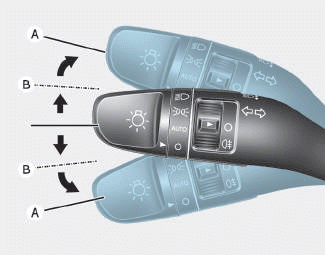
To signal a turn, push down on the lever for a left turn or up for a right turn in position (A). To signal a lane change, move the turn signal lever slightly and hold it in position (B).The lever will return to the OFF position when released or when the turn is completed.

Copyright © 2025 www.hi30.net