Hyundai i-30: Body Side Molding / Roof Side Molding
Repair procedures
•
|
Put on gloves to prevent hand injuries.
|
|
•
|
When removing with a flat-tip screwdriver or remover, wrap protective
tape around the tools to prevent damage to components.
|
|
1. |
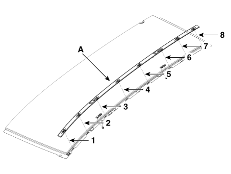
Using a screwdriver or remover, remove the roof side molding (A).
• |
When installing, set up a molding in order of ① - ⑧.
|
|

|
2. |
To install, reverse removal procedure.
• |
Replace any damaged clips (or pin-type retainers).
|
|
|
Repair procedures
Replacement
•
Put on gloves to prevent hand injuries...
Other information:
Components and components location
Components
Audio
Connector Pin Information
NO
Connector A
Connector B
1
Rear left speaker (+)
-
2
Front left speaker (+)
-
3
Front right speaker (+)
-
4
Rear right speaker (+)
Steering wheel key
5
-
-
6
Door open
USB data (HI)
7
IGN 1
USB VCC
8
ILL (+)
-
9
DETENT
-
10
Rear left speaker (-)
MIC signal (+)
11
Front left speaker (-)
ACC
12
Front right speaker (-)
Battery (+)
13
Rear right speaker (-)
-
14
-
-
15
-
-
16
-
Speed
17
ILL (-)
Steering wheel key GND
18
Antenna Power
USB data (LOW)
19
USB GND
20
-
21
-
22
MIC signal (-)
23
-
24
GND
Display Audio
Connector Pin Information
No
Connector A
Connector B
1
Rear door speaker (Left +)
-
2
Rear door speaker (Left -)
Mic_Signal (+)
3
USB Ground
-
4
USB Data_High
-
5
USB Data_Low
Antenna power
6
USB_VCC
Illumination (+)
7
Camera video
MM CAN (High)
8
-
-
9
-
-
10
AUX Audio R
Battery (+)
11
AUX Detect
Battery (+)
12
Steering wheel remote
Ground
13
Front door speaker (Left +)
Ground
14
Front door speaker (Left -)
Mic_Ground
15
Front door speaker (Right -)
Mic_Signal (-)
16
Front door speaker (Right +)
-
17
-
-
18
-
Vehicle speed
19
-
Illumination (-)
20
Camera power ground
MM CAN (Low)
21
Camera video ground
-
22
-
ACC
23
-
-
24
AUX Audio L
-
25
AUX Audio ground
-
26
Steering wheel remote grond
Door open
27
Rear door speaker (Right -)
-
28
Rear door speaker (Right +)
-
29
-
-
30
-
-
31
-
-
32
Camera power ground
IGN 1
33
Camera shield ground
-
34
-
-
35
-
-
36
Camera_Detect
37
-
38
-
Repair procedures
Removal
•
When removing with a flat-tip screwdriver or remover, wrap protective
tape around the tools to prevent damage to components...
Repair procedures
Front wheel alignment
•
When using a commercially available computerized wheel alignment
equipment to inspect the front wheel alignment, always position
the vehicle on a level surface with the front wheels facing
straight ahead...
Categories

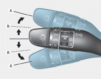
To signal a turn, push down on the
lever for a left turn or up for a right
turn in position (A). To signal a lane
change, move the turn signal lever
slightly and hold it in position (B).The
lever will return to the OFF position
when released or when the turn is
completed.
read more