Hyundai i-30: Smart Key System / Smart Key
Repair procedures
| Smart Key |
Smart Key Code Saving
| 1. |
Connect the DLC cable of GDS to the data link connector (16 pins) in
driver side crash pad lower panel, turn the power on GDS.
|
| 2. |
Select the 'S/W Management' and 'Car model'.
|
| 3. |
Select the 'Integrated Body Control Unit-SMK' and 'Smart Key Code Saving'.
|
| 4. |
Follow the instructions on the screen.
|
 Description and operation
Description
The SMART KEY system is a system that allows the user to access and operate
a vehicle in a very convenient way. To access the vehicle, no traditional key
or remote control unit is needed...
 Smart Key Unit
Components and components location
Components
No
Connector A
Connector B
Connector C
1
-
IGN 2 Relay output
Battery signal
2
SSB Switch 1 input
C CAN (Low)
-
3
Driver door antenna switch input
C CAN (High)
Immoblizer antenna power
4
-
B CAN (High)
Driver out side handle antenna power
5
-
B CAN (Low)
Assist out side handle antenna power
6
-
SSB Illumination (orange)
Bumper antenna power
7
RPM Input
-
Interior antenna 1 power
8
Start signal feedback input
SSB Illumination (+) output
Interior antenna 2 power
9
clutch switch input
ESCL enable output
Interior antenna 3 power
10
-
Battery power
-
11
Starter relay output
IGN 1 Relay output
-
12
Power 1
ESCL COM
-
13
SSB Switch 2 input
EMS COM
ESCL (-) output
14
Assist door antenna switch input
-
Immoblizer antenna ground
15
-
SSB Illumination (-) output
Driver out side handle antenna ground
16
Clutch switch input
SSB LED Output
Assist out side handle antenna ground
17
ESCL unlock swtich input
SSB LED IGN Output
Bumper antenna ground
18
Wheel speed sensor input
External buzzer
Interior antenna 1 ground
19
ACC Input
-
Interior antenna 2 ground
20
IGN 1
ESCL (+) output
Interior antenna 3 ground
21
Brake switch input
-
22
ACC Relay input
GND Power 2
Schematic diagrams
Circuit Diagram
Repair procedures
Removal
Smart Key Unit
1...
Other information:
Hyundai i30 (PD) 2018-2025 Service Manual: Components and components location
..
Hyundai i30 (PD) 2018-2025 Service Manual: Fuel Pump Control Module (FPCM)
Description and operation Description The fuel pump control module (FPCM) is installed on the right side of the fuel tank and controls the DC motor mounted inside the low pressure fuel pump.The module compares instantaneous fuel pressure information measured by the fuel pressure sensor (FPS) with target fuel pressure information provided by the ECM and generates the desired target fuel pressure by controlling the fuel pump motor and regulating fuel flow rate in the low pressure fuel line between the low and high pressure fuel pumps...
Categories
- Manuals Home
- 3rd Generation i30 Owners Manual
- 3rd Generation i30 Service Manual
- LKA system operation
- Exhaust System (DPF) Warning Light. Glow Indicator Light
- To activate the ISG system
- New on site
- Most important about car
Air bag - supplemental restraint system
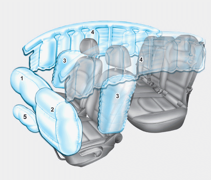
1. Driver’s front air bag
2. Passenger’s front air bag
3. Side air bag*
4. Curtain air bag*
5. Knee air bag*
6. Front passenger air bag ON/OFF
switch

Copyright © 2025 www.hi30.net