Hyundai i-30: Smart Key System / Smart Key Unit
Hyundai i30 (PD) 2018-2025 Service Manual / Body Electrical System / Smart Key System / Smart Key Unit
Components and components location
| Components |
|
No |
Connector A |
Connector B |
Connector C |
|
1 |
- |
IGN 2 Relay output |
Battery signal |
|
2 |
SSB Switch 1 input |
C CAN (Low) |
- |
|
3 |
Driver door antenna switch input |
C CAN (High) |
Immoblizer antenna power |
|
4 |
- |
B CAN (High) |
Driver out side handle antenna power |
|
5 |
- |
B CAN (Low) |
Assist out side handle antenna power |
|
6 |
- |
SSB Illumination (orange) |
Bumper antenna power |
|
7 |
RPM Input |
- |
Interior antenna 1 power |
|
8 |
Start signal feedback input |
SSB Illumination (+) output |
Interior antenna 2 power |
|
9 |
clutch switch input |
ESCL enable output |
Interior antenna 3 power |
|
10 |
- |
Battery power |
- |
|
11 |
Starter relay output |
IGN 1 Relay output |
- |
|
12 |
Power 1 |
ESCL COM |
- |
|
13 |
SSB Switch 2 input |
EMS COM |
ESCL (-) output |
|
14 |
Assist door antenna switch input |
- |
Immoblizer antenna ground |
|
15 |
- |
SSB Illumination (-) output |
Driver out side handle antenna ground |
|
16 |
Clutch switch input |
SSB LED Output |
Assist out side handle antenna ground |
|
17 |
ESCL unlock swtich input |
SSB LED IGN Output |
Bumper antenna ground |
|
18 |
Wheel speed sensor input |
External buzzer |
Interior antenna 1 ground |
|
19 |
ACC Input |
- |
Interior antenna 2 ground |
|
20 |
IGN 1 |
ESCL (+) output |
Interior antenna 3 ground |
|
21 |
Brake switch input |
|
- |
|
22 |
ACC Relay input |
GND Power 2 |
Schematic diagrams
| Circuit Diagram |
Repair procedures
| Removal |
Smart Key Unit
| 1. |
Disconnect the negative (-) battery terminal.
|
| 2. |
Remove the glove box uper cover assembly.
(Refer to Body - "Glove Box uper Cover Assembly")
|
| 3. |
Remove the smart key unit (A)
|
| 4. |
Disconnect the smart key unit connectors (A).
|
Interior 1 Antenna
|

| 1. |
Disconnect the negative (-) battery terminal.
|
| 2. |
Remove the floor console front tray.
(Refer to Body - "Floor Console Assembly")
|
| 3. |
Remove the interior 1 antenna (A) after loosening the mounting nuts
and disconnecting the connector (B).
|
Interior 2 Antenna
| 1. |
Disconnect the negative (-) battery terminal.
|
| 2. |
Remove the floor console assembly.
(Refer to Body - "Floor Consle Assembly.)
|
| 3. |
Remove the rear bumper antenna (A) after loosening the mounting screws
and disconnecting the connector (B).
|
Rear Bumper Antenna
| 1. |
Disconnect the negative (-) battery terminal.
|
| 2. |
Remove the rear bumper cover.
(Refer to Body - "Rear Bumper Cover")
|
| 3. |
Remove the rear bumper antenna (A) after loosening the mounting screws
and disconnecting the connector (B).
|
Buzzer
| 1. |
Disconnect the negative (-) battery terminal.
|
| 2. |
Remove the front left wheel guide.
(Refer to Body - "Front Wheel Guard")
|
| 3. |
Remove the buzzer (B) after disconnecting the connector (A).
|
Door Outside Handle
| 1. |
Disconnect the negative (-) battery terminal.
|
| 2. |
Remove the front outside door handle.
(Refer to Body - "Front Door Outside Handle")
|
| Inspection |
Smart Key Unit
(Refer to Smart Key System - "Smart Key Diagnostic")
Smart Key Switch
(Refer to Smart Key System - "Smart Key Diagnostic")
Antenna
(Refer to Smart Key System - "Smart Key Diagnostic")
Door Outside Handle
| 1. |
Disconnect the front door outside handle connector (A).
|
| 2. |
Check for continuity between terminals No 3 and No 6.
|
| Installation |
Smart Key Unit
| 1. |
Install the smart key unit.
|
| 2. |
Install the smart key unit mounting bolts and connect the connector.
|
| 3. |
Install the glove box.
|
| 4. |
Install the negative (-) battery terminal and check the smart key system.
|
Interior 1 Antenna
| 1. |
Install the interior 1 antenna.
|
| 2. |
Install the glove box uper cover assembly.
(Refer to Body - "Glove Box Uper Cover Assembly")
|
| 3. |
Install the negative (-) battery terminal and check the smart key system.
|
Interior 2 Antenna
| 1. |
Install the interior 2 antenna.
|
| 2. |
Install the floor console assembly.
(Refer to Body - "Floor Console Assembly")
|
| 3. |
Install the negative (-) battery terminal and check the smart key system.
|
Rear bumper antenna
| 1. |
Install the rear bumper antenna.
|
| 2. |
Install the rear bumper cover.
|
| 3. |
Install the negative (-) battery terminal and check the smart key system
|
Door Outside Handle
| 1. |
Install the outside handle.
|
| 2. |
Install the front outside door handle.
|
| 3. |
Install the negative (-) battery terminal and check the smart key system.
|
 Smart Key
Repair procedures
Smart Key
Smart Key Code Saving
1.
Connect the DLC cable of GDS to the data link connector (16 pins) in
driver side crash pad lower panel, turn the power on GDS...
 Smart Key Diagnostic
Repair procedures
Inspection
Self Diagnosis With Scan Tool
It will be able to diagnose defects of SMART KEY system with Diagnostic tool
quickly...
Other information:
Hyundai i30 (PD) 2018-2025 Owner's Manual: Clock
WARNING Do not adjust the clock whilst driving.You may lose your steering control and cause severe personal injury or accidents. Vehicles with Audio system Select the [SETUP/CLOCK ] button on the audio system ➟ Select [Date/Time]. Set time: Set the time displayed on the audio screen...
Hyundai i30 (PD) 2018-2025 Service Manual: Luggage Room Lamp
Repair procedures Removal 1. Disconnect the negative (-) battery terminal. 2. Remove the luggage lamp by using the (-) screw driver. • Be careful not to damage the luggage trim...
Categories
- Manuals Home
- 3rd Generation i30 Owners Manual
- 3rd Generation i30 Service Manual
- Exhaust System (DPF) Warning Light. Glow Indicator Light
- To activate the ISG system
- EPB malfunction indicator
- New on site
- Most important about car
Seat belt warning light
Seat belt warning
Driver’s seat belt warning
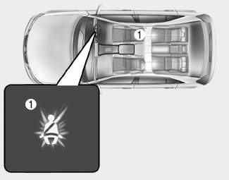
■ Instrument cluster
As a reminder to the driver, the seat belt warning light will illuminate for approximately 6 seconds each time you turn the ignition switch ON regardless of belt fastening.

Copyright © 2025 www.hi30.net