Hyundai i-30: Engine Control System / Differential Pressure Valve (DPV)
Hyundai i30 (PD) 2018-2025 Service Manual / Engine Control / Fuel System / Engine Control System / Differential Pressure Valve (DPV)
Description and operation
| Description |
Differential pressure valve (DPV) is control the pressure difference of EGR
inlet and outlet.
Specifications
| Specification |
[Motor]
|
Item |
Specification |
|
Coil Resistance (Ω) |
2.85 - 3.05 [20°C (68°F)] |
[Position Sensor]
|
Item |
Specification |
|
Operating Voltage (V) |
4.5 - 5.5 |
|
Output Voltage (V) |
0.25 - 4.75 |
Schematic diagrams
| Circuit Diagram |
Harness Connector

Repair procedures
| Inspection |
[Motor]
| 1. |
Turn the ignition switch OFF.
|
| 2. |
Disconnect the differential pressure valve connector.
|
| 3. |
Check that the differential pressure valve is stuck by foreign material.
|
| 4. |
Measure resistance between motor 1 and 2 control terminals of the motor.
|
| 5. |
Check that the resistance is within the specification.
|
| Removal |
| 1. |
Turn the ignition switcg OFF, and disconnect the battery negative (-)
terminal.
|
| 2. |
Remove the air cleaner assembly.
(Refer to Engine Mechanical System - "Air Cleaner")
|
| 3. |
Disconnect the differential pressure valve connector (A).
|
| 4. |
Remove the differential pressure valve after loosening the mounting
bolt (B).
|
| Installation |
|

| 1. |
Install in the reverse order of removal.
|
 Exhaust Gas Temperature Sensor (EGTS)
Description and operation
Description
Exhaust Gas Temperature Sensor (EGTS) is installed on Gasoline Particulate Filter
(GPF) senses the temperature of exhaust gas flowing into...
 Purge Control Solenoid Valve (PCSV)
Description and operation
Description
Purge Control Solenoid Valve (PCSV) is installed on the surge tank and controls
the passage between the canister and the intake manifold...
Other information:
Hyundai i30 (PD) 2018-2025 Owner's Manual: Vehicle Stability Management (VSM)
The Vehicle Stability Management (VSM) is a function of the Electronic Stability Control (ESC) system. It helps ensure the vehicle stays stable when accelerating or braking suddenly on wet, slippery and rough roads where traction over the four tyres can suddenly become uneven...
Hyundai i30 (PD) 2018-2025 Service Manual: Tail Gate Trim
Components and components location Component Location 1. Tail Gate trim Repair procedures Replacement [Tail Gate lower trim] • Put on gloves to prevent hand injuries...
Categories
- Manuals Home
- 3rd Generation i30 Owners Manual
- 3rd Generation i30 Service Manual
- Cruise control
- Engine coolant
- Shift-lock system. Shift-lock release
- New on site
- Most important about car
Gauges and meters
Speedometer

The speedometer indicates the speed of the vehicle and is calibrated in kilometers per hour (km/h) and/or miles per hour (MPH).
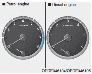
Tachometer

Copyright © 2025 www.hi30.net