Hyundai i-30: Intake and Exhaust System / EGR Cooler
Components and components location
| Components |
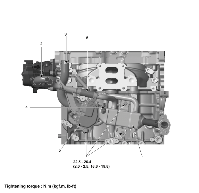
| 1. EGR Cooler
assembly 2. EGR cooler water inlet hose 3. EGR gas outlet hose |
4. EGR gas temp
sensor 5. EGR valve 6. EGR cooler water outlet hose |
Repair procedures
| Removal and Installation |
|

| 1. |
Disconnect the battery negative terminal.
|
| 2. |
Drain the engine coolant.
(Refer to Cooling System - "Coolant")
|
| 3. |
Remove the catalytic converter (WCC).
(Refer to Intake and Exhaust System - "Torbo Charger & Exhaust Manifold")
|
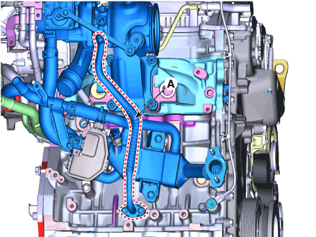
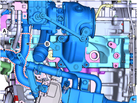
| 4. |
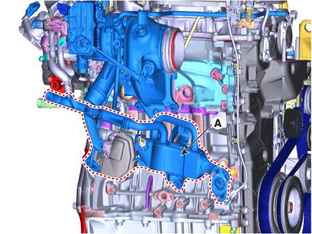
Disconnect the EGR valve connector (A) and EGR temp sensor connector
(B).
|
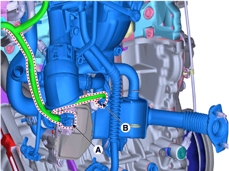
| 5. |
Remove the turbo charger oil drain pipe (A).
|
| 6. |
Disconnect the EGR cooler water inlet hose (A) and EGR gas outlet hose
(B)
|
| 7. |
Remove the EGR Cooler assembly (A).
|
| 8. |
Install in the reverse order of removal.
|
| 9. |
Fill the radiator with coolant.
(Refer to Cooling System - "Coolant")
|
 Muffler
Components and components location
Components
1. Front muffler
2. GPF
3. Center muffler
4. Rear muffler
5...

Other information:
Hyundai i30 (PD) 2018-2025 Owner's Manual: Driving with a trailer
Towing a trailer requires a certain amount of experience. Before setting out for the open road, you must get to know your trailer. Acquaint yourself with the feel of handling and braking with the added weight of the trailer. And always keep in mind that the vehicle you are driving is now longer and not nearly as responsive as your vehicle is by itself...
Hyundai i30 (PD) 2018-2025 Owner's Manual: Low Tyre Pressure. Turn FUSE SWITCH on
Low Tyre Pressure This warning message is displayed if the tyre pressure is low. The corresponding tyre on the vehicle will be illuminated. Turn FUSE SWITCH on This warning message is displayed if the fuse switch located on the fuse box under the steering wheel is OFF...
Categories
- Manuals Home
- 3rd Generation i30 Owners Manual
- 3rd Generation i30 Service Manual
- To activate the ISG system
- EPB malfunction indicator
- Trip computer
- New on site
- Most important about car
Warning light and message
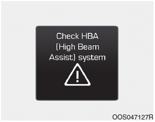
When the High Beam Assist (HBA)
System is not working properly, the
warning message will come on for a
few second. After the message disappears,
the master warning light ( )
will illuminate.
)
will illuminate.

Copyright © 2025 www.hi30.net