Hyundai i-30: Engine Control System / ETC (Electronic Throttle Control) System
Hyundai i30 (PD) 2018-2025 Service Manual / Engine Control / Fuel System / Engine Control System / ETC (Electronic Throttle Control) System
Description and operation
| Description |
The Electronic Throttle Control (ETC) System consists of a throttle body with
an integrated control motor and throttle position sensor (TPS). Instead of the
traditional throttle cable, an Accelerator Position Sensor (APS) is used to
receive driver input. The ECM uses the APS signal to calculate the target throttle
angle; the position of the throttle is then adjusted via ECM control of the
ETC motor. The TPS signal is used to provide feedback regarding throttle position
to the ECM. Using ETC, precise control over throttle position is possible; the
need for external cruise control modules/cables is eliminated.

Specifications
| Specification |
[Throttle Position Sensor (TPS)]
▷ Type : IC Rotate Sensor Type
▷ Specification
[ETC Motor]
|
Item |
Specification |
|
Coil Resistance (Ω) |
1.29 - 1.57 [20°C (68°F)] |
Troubleshooting
| Fail-Safe Mode |
|
Item |
Fail-Safe |
|
|
ETC Motor |
Throttle valve stuck at 9.2° |
|
|
TPS |
TPS1 fault |
ECM looks at TPS2 |
|
TPS2 fault |
ECM looks at TPS1 |
|
|
TPS 1, 2 fault |
Throttle valve stuck at 9.2° |
|
|

Schematic diagrams
| Schematic Diagram |
| Circuit Diagram |
Harness Connector
Repair procedures
| Inspection |
Throttle Position Sensor (TPS)
| 1. |
Connect the diagnostic tool on the Data Link Connector (DLC).
|
| 2. |
Start the engine and measure the output voltage of TPS 1 and 2 at C.T.
and W.O.T.
|
ETC Motor
| 1. |
Turn the ignition switch OFF.
|
| 2. |
Disconnect the ETC module connector.
|
| 3. |
Measure resistance between the ETC module terminals 1 and 2.
|
| 4. |
Check that the resistance is within the specification.
|
| Removal |
| 1. |
Turn the ignition switch OFF and disconnect the battery negative (-)
cable.
|
| 2. |
Disconnect the ETC Module Connector (A).
|
| 3. |
Remove the intercooler outlet hose.
(Refer to Engine Mechanical System - "Intercooler")
|
| 4. |
Remove the ETC module (A) after loosening the mounting bolts.
|
| Installation |
|

| 1. |
Install in the reverse order of removal.
|
| Cleaning |
| 1. |
Remove the ETC Module.
(Refer to Engine Control System - "ETC System")
|
| 2. |
Keep the ETC module plate (A) open.
|
| 3. |
Clean the pollutant in the throttle body with a soft cloth moistened
with cleaning fluid.
|
| 4. |
After cleaning, re-install the ETC module and then perform the ETC module
learning procedure.
(Refer to Engine Control System - "ETC System" - Adjustment)
|
| Adjustment |
ETC Module Learning Procedure
Be sure to perform the ETC module learning procedure when replacing or re-installing
the ETC module.
| 1. |
Wait for 1 minute with the ignition switch ON.
|
| 2. |
Start the engine and hold the idle status for 15 minutes.
|
| 3. |
Waif for 1 minute with the ignition switch OFF.
|
| 4. |
Restart the engine, and check that the idle speed is stable.
|
 Mass Air Flow Sensor (MAFS)
Description and operation
Description
MAFS uses a hot-film type sensing element to measure the mass of intake air
entering the engine, and send the signal to ECM...
 Manifold Absolute Pressure Sensor (MAPS)
Description and operation
Description
Manifold Absolute Pressure Sensor (MAPS) is a speed-density type sensor and
is installed on the surge tank...
Other information:
Hyundai i30 (PD) 2018-2025 Owner's Manual: Dimensions, Engine, Bulb wattage
D..
Hyundai i30 (PD) 2018-2025 Service Manual: Accelerator Position Sensor (APS)
Description and operation Description Accelerator Position Sensor (APS) is installed on the accelerator pedal module and detects the rotation angle of the accelerator pedal. The APS is one of the most important sensors in engine control system, so it consists of the two sensors which adapt individual sensor power and ground line...
Categories
- Manuals Home
- 3rd Generation i30 Owners Manual
- 3rd Generation i30 Service Manual
- Recommended lubricants and capacities
- FCA sensor
- Exhaust System (DPF) Warning Light. Glow Indicator Light
- New on site
- Most important about car
Power windows
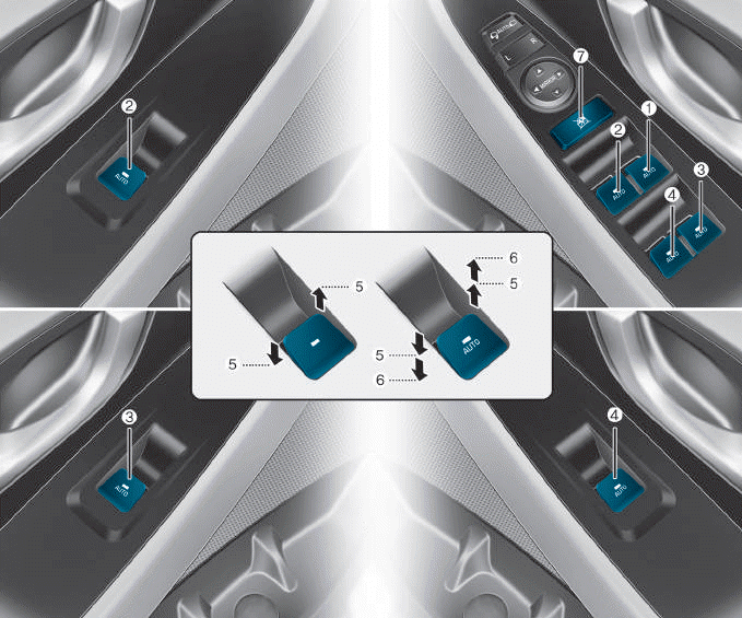
(1) Driver’s door power window
switch
(2) Front passenger’s door power
window switch
(3) Rear door (right) power window
switch
(4) Rear door (left) power window
switch
(5) Window opening and closing
(6) Automatic power window
(7) Power window lock switch

Copyright © 2025 www.hi30.net