Hyundai i-30: Engine Control System / Manifold Absolute Pressure Sensor (MAPS)
Hyundai i30 (PD) 2018-2025 Service Manual / Engine Control / Fuel System / Engine Control System / Manifold Absolute Pressure Sensor (MAPS)
Description and operation
| Description |
Manifold Absolute Pressure Sensor (MAPS) is a speed-density type sensor and
is installed on the surge tank. It senses absolute pressure of the surge tank
and transfers the analog signal proportional to the pressure to the ECM. By
using this signal, the ECM calculates the intake air quantity and engine speed.
The MAPS consists of a piezo-electric element and a hybrid IC amplifying the
element output signal. The element is silicon diaphragm type and adapts pressure
sensitive variable resistor effect of semi-conductor. Because 100% vacuum and
the manifold pressure apply to both sides of the sensor respectively, this sensor
can output analog signal by using the silicon variation proportional to pressure
change.
Specifications
| Specification |
|
Pressure [kPa (kg/cm², psi)] |
Output Voltage (V) |
|
10 (0.10, 1.45) |
0.5 |
|
40 (0.41, 5.80) |
0.913 |
|
80 (0.82, 11.60) |
1.465 |
|
120 (1.22, 17.40) |
2.017 |
|
160 (1.63, 23.21) |
2.569 |
|
200 (2.04, 29.01) |
3.12 |
|
220 (2.24, 31.91) |
3.396 |
|
240 (2.45, 34.81) |
3.672 |
|
280 (2.86, 40.61) |
4.224 |
|
300 (3.06, 43.51) |
4.5 |
Troubleshooting
| Signal Waveform |
Schematic diagrams
| Circuit Diagram |
Harness Connector
Repair procedures
| Inspection |
| 1. |
Connect the diagnostic tool on the Data Link Connector (DLC).
|
| 2. |
Measure the output voltage of the MAPS at idle and IG ON.
|
| Removal |
| 1. |
Turn the ignition switch OFF and disconnect the battery negative (-)
cable.
|
| 2. |
Disconnect the manifold absolute pressure sensor connector (A).
|
| 3. |
Remove the installation bolt (B), and then remove the sensor from the
surge tank.
|
| Installation |
|

|
| 1. |
Install in the reverse order of removal.
|
 ETC (Electronic Throttle Control) System
Description and operation
Description
The Electronic Throttle Control (ETC) System consists of a throttle body with
an integrated control motor and throttle position sensor (TPS)...
 Intake Air Temperature Sensor (IATS)
Description and operation
Description
Intake Air Temperature Sensor (IATS) is included inside Manifold Absolute Pressure
Sensor and detects the intake air temperature...
Other information:
Hyundai i30 (PD) 2018-2025 Owner's Manual: ESC operation
ESC ON condition When the ignition switch is in the ON position, the ESC and the ESC OFF indicator lights illuminate for approximately three seconds and goes off, then the ESC is turned on. When operating When the ESC is in operation, the ESC indicator light blinks: When you apply your brakes under conditions which may lock the wheels, you may hear sounds from the brakes, or feel a corresponding sensation in the brake pedal...
Hyundai i30 (PD) 2018-2025 Service Manual: Master Cylinder
Components and components location Components [LHD] 1. Reservoir cap 2. Reservoir 3. Brake booster 4. Master cylinder 5. Push rod [RHD] 1. Reservoir cap 2...
Categories
- Manuals Home
- 3rd Generation i30 Owners Manual
- 3rd Generation i30 Service Manual
- Drive mode integrated control system
- Engine compartment
- Battery replacement
- New on site
- Most important about car
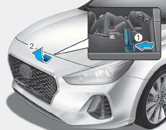
Bonnet
Opening the bonnet
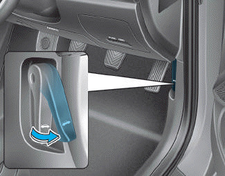
1. Park the vehicle and set the parking brake.
2. Pull the release lever to unlatch the bonnet. The bonnet should pop open slightly.

Copyright © 2025 www.hi30.net