Hyundai i-30: Engine Control System / Mass Air Flow Sensor (MAFS)
Description and operation
MAFS uses a hot-film type sensing element to measure the mass of intake air
entering the engine, and send the signal to ECM.
A large amount of intake air represents acceleration or high load conditions
while a small amount of intake air represents deceleration or idle.
The ECM uses this information to control the EGR solenoid valve and correct
the fuel amount.
Specifications
Air Flow (kg/h)
|
SENT
|
-40
|
1
|
-30
|
645
|
-20
|
1381
|
-15
|
1788
|
-12
|
2047
|
-10
|
2228
|
-8
|
2416
|
-6
|
2613
|
0
|
3300
|
6
|
4122
|
8
|
4359
|
10
|
4585
|
12
|
4801
|
15
|
5112
|
20
|
5599
|
30
|
6480
|
40
|
7252
|
50
|
7922
|
60
|
8501
|
70
|
9004
|
80
|
9444
|
90
|
9833
|
105
|
10341
|
120
|
10780
|
140
|
11284
|
160
|
11719
|
180
|
12103
|
200
|
12446
|
220
|
12756
|
250
|
13174
|
280
|
13547
|
310
|
13884
|
340
|
14191
|
370
|
14475
|
400
|
14738
|
440
|
15063
|
480
|
15363
|
560
|
15901
|
600
|
16145
|
Schematic diagrams
Harness Connector
Repair procedures
|
1. |
Using diagnostic tool, inspect the signal waveform of the MAPS at idle
and acceleration.
|
Specification : Refer to "Waveform"
|
|
|
2. |
Check the MAFS visually.
| –
|
Mounting direction correct.
|
| –
|
Any contamination, corrosion or damage on connector.
|
| –
|
Air cleaner's clogging or wet.
|
| –
|
MAFS cylinder's deforming or blocking by any foreign material.
|
|
|
3. |
Check any leakage on intake system and intercooler system.
|
|
1. |
Turn the ignition switch OFF and disconnect the battery (-) cable.
|
|
2. |
Disconnect the mass air flow sensor connector (A) and the installation
clamp (B).
|
|
3. |
Remove the mass air flow sensor (C) after loosening mounting bolt.
|
Tightening Torque :
9.8 - 11.8 N.m (1.0 - 1.2 kgf.m, 7.2 - 8.7 lb.ft)
|
|
| •
|
Install the component with the specified torques.
|
| •
|
Note that internal damage may occur when the component is dropped.
In this case, use it after inspecting.
|
|
| •
|
Be careful not to damage or deformation the sensing element
and front grid.
|
| •
|
Insert the sensor in the installation hole and be careful not
to damage when installation.
|
|
|
1. |
Install in the reverse order of removal.
|
Schematic diagrams
ECM Terminal and Input /
Output signal
ECM Harness Connector
ECM Terminal Function
Connector [A]
Terminal
Description
1
Fuel Pressure Regulator Valve (FPRV) [High] Control
2
Integrated Thermal Management Module (ITM) Motor (+)
3
Integrated Thermal Management Module (ITM) Motor (-)
4
Exhaust Gas Temperature Sensor (EGTS) #2 (T4) Ground [GPF Type]
5
Engine Coolant Temperature Sensor (ECTS) #1 Ground
6
-
7
Engine Coolant Temperature Sensor (ECTS) #2 Ground
8
Differential Pressure Valve (DPV) Ground
9
Rail Pressure Sensor (RPS) Ground
10
Exhaust Gas Temperature Sensor (EGTS) Ground
11
Manifold Absolute Pressure Sensor (MAPS) Ground
12
Electric Waste Gate Control Actuator (EWGA) Ground
13
EGR Pressure Sensor Ground
14
Oil Pressure & Temperature Sensors (OPTS) Ground
15
Electric Exhaust Gas Recirculation (EEGR) Control Valve Ground
16
-
17
A/C Pressure Transducer (APT) Ground
18
Sensor Power (+5V) (Camshaft Position Sensor (CMPS) [Bank 1 / Intake, Exhaust])
19
Sensor Power (+5V) (Manifold Absolute Pressure Sensor (MAPS))
Sensor Power (+5V) (Electric Exhaust Gas Recirculation (EEGR))
Sensor Power (+5V) (Crankshaft Position Sensor (CKPS))
20
Sensor Power (+5V) (Oil Pressure & Temperature Sensors (OPTS))
Sensor Power (+5V) (Electric Throttle Control Module (ETC))
Sensor Power (+5V) (Rail Pressure Sensor (RPS))
21
Throttle Position Sensor (TPS) Ground
22
Electric Exhaust Gas Recirculation (EEGR) Control Valve Motor (+)
23
Electric Exhaust Gas Recirculation (EEGR) Control Valve Motor (-)
24
Knock Sensor (KS ) Shield Ground
25
-
26
Ignition Coil (Cylider #3) Control
27
-
28
-
29
Exhaust Gas Temperature Sensor (EGTS) #1 (T3) Ground [GPF Type]
30
-
31
-
32
-
33
EGR Pressure Sensor Signal
34
-
35
Integrated Thermal Management Module (ITM) Motor Ground
36
-
37
Camshaft Position Sensor (CMPS) [Bank 1 / Intake] Signal
38
-
39
Electric Waste Gate Control Actuator (EWGA) Signal
40
Sensor Power (+5V) (EGR Pressure Sensor)
Sensor Power (+5V) (Electric Waste Gate Control Actuator (EWGA))
41
Sensor Power (+5V) (Accelerator Position Sensor (APS #1))
42
Sensor Power (+5V) (Brake Booster Vacuum Pressure Sensor (BBVPS))
Sensor Power (+5V) (A/C Pressure Transducer (APT))
43
Injector (Cylinder #3) [+] Control
44
Injector (Cylinder #2) [+] Control
45
-
46
-
47
CCP-CAN [High]
48
Ignition Coil (Cylinder #1) Control
49
-
50
Neutral Switch [With ISG]
51
-
52
-
53
-
54
Exhaust Gas Temperature Sensor (EGTS) #1 (T3) Signal [GPF Type]
55
-
56
Exhaust Gas Temperature Sensor (EGTS) #2 (T4) Signal [GPF Type]
57
-
58
Differential Pressure Sensor (DPS) Signal
59
Exhaust Gas Temperature Sensor (EGTS) Signal
60
Camshaft Position Sensor (CMPS) [Bank 1 / Exhaust] Ground
61
Mass Air Flow Sensor (MAFS) Signal
62
-
63
Engine Speed Signal Output
64
Injector (Cylinder #1) [+] Control
65
Injector (Cylinder #4) [+] Control
66
Injector (Cylinder #3) [-] Control
67
Injector (Cylinder #4) [-] Control
68
Ignition Coil (Cylider #2) Control
69
CCP-CAN [Low]
70
Camshaft Position Sensor (CMPS) [Bank 1 / Exhaust] Signal
71
Crankshaft Position Sensor (CKPS) Ground
72
Ignition Lock Switch [M/T & Without Smart Key]
73
Oil Pressure Sensor (OPS) Signal
74
Intake Air Temperature Sensor (IATS) Signal
75
Engine Coolant Temperature Sensor (ECTS) #1 Signal
76
Engine Coolant Temperature Sensor (ECTS) #2 Signal
77
Electric Exhaust Gas Recirculation (EEGR) Control Valve Signal
78
Differential Pressure Valve (DPV) Signal
79
Throttle Position Sensor (TPS) #2 Signal
80
Rail Pressure Sensor (RPS) Signal
81
-
82
Integrated Thermal Management Module (ITM) Motor Signal
83
Mass Air Flow Sensor (MAFS) Ground
84
A/C Pressure Transducer (APT) Signal
85
-
86
Injector (Cylinder #2) [-] Control
87
Injector (Cylinder #1) [-] Control
88
Fuel Pressure Regulator Valve (FPRV) [Low] Control
89
Differential Pressure Sensor (DPS) Ground
90
Ignition Coil (Cylinder #4) Control
91
Crankshaft Position Sensor (CKPS) Signal
92
-
93
Heated Oxygen Sensor (HO2S) [Bank 1 / Sensor 2] Ground
94
-
95
Heated Oxygen Sensor (HO2S) [Bank 1 / Sensor 2] Signal
96
-
97
Oil Temperature Sensor (OTS) Signal
98
Throttle Position Sensor (TPS) #1 Signal
99
-
100
-
101
Manifold Absolute Pressure Sensor (MAPS) Signal
102
Camshaft Position Sensor (CMPS) [Bank 1/Intake] Ground
103
-
104
Knock Sensor (KS) Signal
105
Knock Sensor (KS) Ground
Connector [B]
Terminal
Description
1
Chassis Ground
2
Chassis Ground
3
Battery Power (B+) (Battery)
4
Chassis Ground
5
Battery Power (B+) (Main Relay)
6
Battery Power (B+) (Main Relay)
7
-
8
-
9
Sensor Power (+5V) (Integrated Thermal Management Module (ITM) Motor)
Sensor Power (+5V) (Mass Air Flow Sensor (MAFS))
10
Sensor Power (+5V) (Accelerator Position Sensor (APS) #2)
11
Boost Pressure Sensor (BPS) Signal Input
12
Accelerator Position Sensor (APS) #2 Ground
13
Accelerator Position Sensor (APS) #1 Ground
14
Brake Booster Vacuum Pressure Sensor (BBVPS) Ground [With ISG]
15
-
16
Boost Pressure Sensor (BPS) Ground
17
Fuel Level Sender (FLS) Signal
18
Accelerator Position Sensor (APS #2) Signal
19
-
20
-
21
-
22
RCV Control Solenoid Valve Control
23
Cooling Fan Relay [PWM] Control
24
Electric Waste Gate Control Actuator (EWGA) DC Motor (+) Control
25
Electric Waste Gate Control Actuator (EWGA) DC Motor (-) Control
26
Ignition Switch Signal Input
27
Sensor Power (+5V) (Differential Pressure Sensor (DPS))
Sensor Power (+5V) (Differential Pressure Valve (DPV))
Sensor Power (+5V) (Boost Pressure Sensor (BPS))
28
-
29
-
30
Brake Light Switch Signal Input
31
Brake Test Switch Signal Input
32
Accelerator Position Sensor (APS #1) Signal
33
-
34
ISG OFF Switch Signal Input [With ISG]
35
Start Signal Input
36
-
37
Fuel Pump Relay Control [W/O Smart Key]
38
DC/DC Converter (LDC) Control [With ISG]
39
-
40
Variable Oil Pump Valve Control
41
ETC Motor [+] Control
42
ETC Motor [-] Control
43
-
44
LIN communication signal input
45
C-CAN (Low)
46
-
47
-
48
Clutch Switch [M/T]
49
Wiper Switch Signal Input
50
Blower Motor MAX Input
51
Start Relay Control (Low Side)
52
-
53
-
54
Rear Defrost Switch Signal Input
55
-
56
-
57
-
58
Differential Pressure Valve (DPV) DC Motor (+) Control
59
Differential Pressure Valve (DPV) DC Motor (-) Control
60
Battery Power (B+) (Battery)
61
LIN Communication Signal input
62
C-CAN (High)
63
Brake Booster Vacuum Pressure Sensor (BBVPS) Signal [With ISG]
64
Heated Oxygen Sensor (HO2S) [Bank 1 / Sensor 1] VS+ (NERNST Cell Voltage)
65
Heated Oxygen Sensor (HO2S) [Bank 1 / Sensor 1] Rc (Compensative Resistance)
66
Heated Oxygen Sensor (HO2S) [Bank 1 / Sensor 1] Rc/Rp (Pump Cell Voltage)
67
Heated Oxygen Sensor (HO2S) [Bank 1 / Sensor 1] VS-/IP- (Common Ground for
VS, IP)
68
-
69
A/C Compressor Relay Control
70
-
71
Start Relay Control (High side)
72
-
73
-
74
Engine Control Relay Control
75
Heated Oxygen Sensor (HO2S) [Bank 1 / Sensor 1] Heater Control
76
Heated Oxygen Sensor (HO2S) [Bank 1 / Sensor 2] Heater Control
77
Vehicle Speed Signal Input
78
CCP-CAN [High]
79
CCP-CAN [Low]
80
-
81
-
82
-
83
Purge Control Solenoid Valve (PCSV) Control
84
Fuel Pump Relay Control [With Smart Key]
85
ISG OFF Switch (IND...
Description and operation
Description
The Electronic Throttle Control (ETC) System consists of a throttle body with
an integrated control motor and throttle position sensor (TPS)...
Other information:
Components and components location
Component Location
1. Sunvisor
2. Retainer
Repair procedures
Replacement
•
Put on gloves to prevent hand injuries...
Repair procedures
Removal and Installation
1.
Remove the engine room under cover.
(Refer to Engine and Transaxle Assembly - "Engine Room Under Cover")
2.
Drain the coolant...
Categories
If your vehicle is equipped with a
sunroof, you can slide or tilt your
sunroof with the sunroof control lever
located on the overhead console.
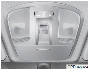
The ignition switch must be in the ON
position before you can open or
close the sunroof.
The sunroof can be operated for
approximately 30 seconds after the
ignition key is removed or turned to
the ACC or LOCK(or OFF) position.
However, if the front door is opened,
the sunroof cannot be operated even
within 30 seconds.
read more

 Engine Control Module (ECM)
 ETC (Electronic Throttle Control) System