Hyundai i-30: Front Door / Front Door Module
Hyundai i30 (PD) 2018-2025 Service Manual / Body (Interior and Exterior) / Front Door / Front Door Module
Components and components location
| Component Location |
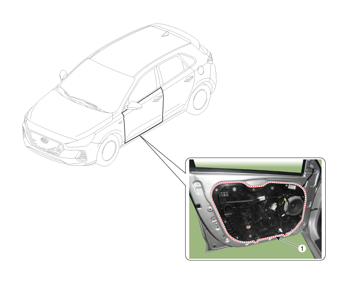
| 1. Front door
module |
Repair procedures
| Replacement |
| 1. |
Remove the front door window glass.
(Refer to Front Door - "Front Door Window Glass")
|
| 2. |
Remove the front door outside handle.
(Refer to Front Door - "Front Door Outside Module")
|
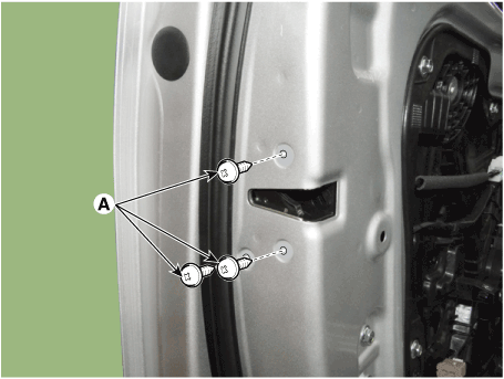
| 3. |
Disconnect the front door main connector (A).
|
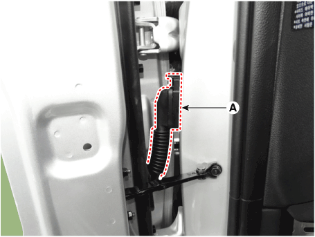
| 4. |
Loosen the front door outside handle base mounting bolt (A).
|
| 5. |
Disconnect the outside rear view mirror connector (A).
|
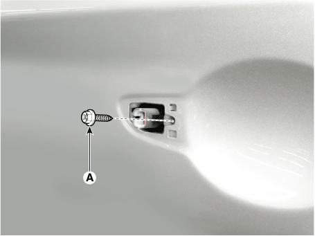
| 6. |
Loosen the front door latch mounting screws (A).
|
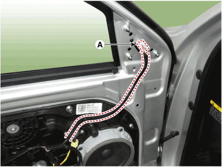
| 7. |
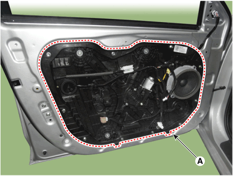
Loosen the mounting bolts and remove the front door module (A).
|
| 8. |
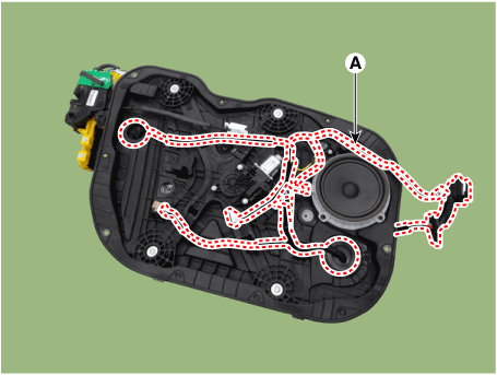
Disconnect the connectors and front door module wiring harness (A).
|
| 9. |
Remove the front door latch assembly.
(Refer to Front Door - "Front Door Latch")
|
| 10. |
Remove the front door speaker
(Refer to Body Electrical System - "Speaker")
|
| 11. |
Remove the front power window motor.
(Refer to Body Electrical System - "Power Window Motor")
|
| 12. |
Remove the side impact sensor.
(Refer to Restraint - "Side Impact Sensor (SIS)")
|
| 13. |
To install, reverse removal procedure.
|

 Front Door Window Glass
Components and components location
Component Location
1. Front door
window glass
Repair procedures
Replacement
1...
 Front Door Outside Handle
Components and components location
Component Location
1. Front door
outside handle
Repair procedures
Replacement
1...
Other information:
Hyundai i30 (PD) 2018-2025 Service Manual: Relay Box (Passenger Compartment)
Components and components location Component Location [Interior Junction Block] IGPM(Integrated Gateway & Power Control Module) Circuit (IGPM) Description and operation Description Communication Network Diagram Abbreviation Expalnation ECM Engine Control Module TCU Transmission Control Unit MDPS Motor Driven Power Steering AEB Autonomous Emergency Braking LKAS Lane Keeping Assist System FPS Fuel Pump Control module RR CAMERA Rear View Carmera VACUUM Vacuum Pump CLUSTER Cluster Module ACU Airbag Control Unit DATC Dual Automatic Temp Control MTC Temp Control OCS Occupant Classification System VDC Vehicle Dynamic Control BSD Blind Spot Detection AMP Amplifier AVN Head Unit (Audio / AVN) SMK Smart Key Unit WPC Wireless Power Charger IMS Integrated Memory System DDM Driver Door Module ADM Assist Door Module BCM Body Control Module B-CAN Body Controller Area Network P-CAN Powertrain Controller Area Network M-CAN Multi media Controller Area Network C-CAN Chassis Controller Area Network Integrated Gateway & Power control Module (IGPM) Integrated Gateway & Power control Module (IGPM) is a module that performs the function of conventional Junction Block and some functions of BCM...
Hyundai i30 (PD) 2018-2025 Owner's Manual: How does the air bags system operate?
The SRS consists of the following components: (1) Driver's front air bag module/ Driver’s knee air bag module (2) Passenger's front air bag module (3) Side air bag modules/ Side impact sensors (4) Curtain air bag modules (5) Rear Retractor pre-tensioner (6) Retractor pre-tensioner assemblies (7) Air bag warning light (8) SRS control module (SRSCM)/ Rollover sensor (9) Front impact sensors (10) Side pressure sensors (11) Passenger’s front air bag ON/OFF indicator (12) Passenger’s front air bag ON/OFF switch The SRSCM continually monitors all SRS components whilst the ignition switch is ON to determine if a crash impact is severe enough to require air bag deployment or pre-tensioner seat belt deployment...
Categories
- Manuals Home
- 3rd Generation i30 Owners Manual
- 3rd Generation i30 Service Manual
- EPB malfunction indicator
- Theft-alarm system
- Trip computer
- New on site
- Most important about car
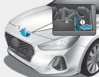
Bonnet
Opening the bonnet
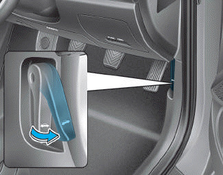
1. Park the vehicle and set the parking brake.
2. Pull the release lever to unlatch the bonnet. The bonnet should pop open slightly.

Copyright © 2025 www.hi30.net