Hyundai i-30: Heater / Heater Unit
Components and components location
| Component Location |
| 1. Heater unit
assembly |
| Components |
| 1. Heater
core cover 2. Heater core & seal assembly 3. Mode control actuator 4. Temperature control actuator [LH] 5. PTC Heater [DSL] 6. Air guide [LH] 7. Center duct seal 8. Heater unit pad 9. Deforster door assembly 10. Vent door assembly |
11. Floor
door assembly 12. Console floor door assembly 13. Heater case [LH] 14. Console cover 15. Evaporator lower insulator 16. Evaporator core cover 17. Drain hose 18. Heater case [RH] 19. Separator 20. Air guide [RH] |
21. Evaporator
temperature sensor 22. Inhale hose 23. Temperature control actuator [RH] 24. Auto defogging actuator 25. Evaporator core assembly 26. PTC Heater [GSL] 27. Duct sensor 28. Shower duct [LH] 29. Shower duct [RH] |
Repair procedures
| Replacement |
|

| 1. |
Disconnect the negative (-) battery terminal.
|
| 2. |
Recover the refrigerant with a recovery / recycling / charging station.
|
| 3. |
When the engine is cool, drain the engine coolant from the radiator.
(Refer to Engine Mechanical System - "Coolant")
|
| 4. |
Remove the engine cover.
(Refer to Engine Mechanical System - "Engine Cover")
|
| 5. |
Remove the bolts and the expansion valve (A) from the evaporator core.
|

| 6. |
Disconnect the heater hoses (A) from the heater unit.
|
| 7. |
Loosen the cowl cross member mounting bolts.
|
| 8. |
Remove the floor console assembly.
(Refer to Body - "Floor Console Assembly")
|
| 9. |
Remove the crash pad lower panel.
(Refer to Body - "Crash Pad Lower Panel")
|
| 10. |
Remove both sides of the front pillar trim.
(Refer to Body - "Front Pillar Trim")
|
| 11. |
Remove the cowl side trim.
(Refer to Body - "Cowl Side Trim")
|
| 12. |
Remove the steering column shroud lower panel.
(Refer to Body - "Steering Column Shroud Panel")
|
| 13. |
Remove the steering wheel.
(Refer to Steering System - "Steering Wheel")
|
| 14. |
Remove the multifunction switch.
(Refer to Body Electrical System - "Multifunction Switch")
|
| 15. |
Lower the steering column after loosening the mounting bolts.
(Refer to Steering System - "Steering Column and Shaft")
|
| 16. |
Remove the shift lever assembly.
(Refer to Automatic Transmission System - "Shift Lever")
|
| 17. |
Remove the crash pad under cover (A) [RH].
|
| 18. |
Remove the rear air duct (A).
|
| 19. |
Separate the floor carpet (A) to obtain space for removing the rear
heating duct.
|
| 20. |
Loosen the mounting nut and remove the rear air duct (A).
|
| 21. |
Disconnect the airbag control module (SRSCM) connector (A).
|
| 22. |
Disconnect the junction box connectors (A).
|
| 23. |
Disconnect the multi box connectors (A).
[Driver's side]
[Passenger's side]
|
| 24. |
Disconnect the connectors (A) and the mounting clips in the front pillar.
[Driver's side]
[Passenger's side]
|
| 25. |
Loosen the blower unit mounting bolts.
|
| 26. |
Remove the drain hose (A).
|
| 27. |
After loosening the bolts and nuts remove the main crash pad and cowl
cross bar assembly (A) together.
|
| 28. |
Disconnect the heater & blower unit connectors.
|
| 29. |
Loosen the heater & blower unit mounting bolt (A).
|
| 30. |
Remove the heater and blower unit (A) from the crash pad (B) after loosening
the mounting nuts.
|
| 31. |
Separate the blower unit (A) from the heater unit (B) after loosening
the screws.
|
| 32. |
To install, reverse the removal procedure.
|
 Heater
..
 Heater Core
Repair procedures
Replacement
1.
Disconnect the negative (-) battery terminal.
2.
Remove the heater and blower assembly...
Other information:
Hyundai i30 (PD) 2018-2025 Service Manual: Components and components location
..
Hyundai i30 (PD) 2018-2025 Service Manual: AEB Radar
Repair procedures Removal 1. Remove the bumper. (Refer to Body - "Front Bumper") 2. Disconnect the smart cruise control unit connector (A). 3...
Categories
- Manuals Home
- 3rd Generation i30 Owners Manual
- 3rd Generation i30 Service Manual
- Battery replacement
- EPB malfunction indicator
- Theft-alarm system
- New on site
- Most important about car
Turn signals and lane change signals
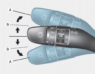
To signal a turn, push down on the lever for a left turn or up for a right turn in position (A). To signal a lane change, move the turn signal lever slightly and hold it in position (B).The lever will return to the OFF position when released or when the turn is completed.

Copyright © 2025 www.hi30.net