Hyundai i-30: Dual Clutch Transmission Control System / Inhibitor Switch
Description and operation
| • |
The inhibitor switch is installed on top of transmission, and is connected
to the shift lever through shift cable.
|
| • |
Inhibitor switch signals (S1, S2, S3, S4) are transmitted to the TCM
according to the driver's shift lever control.
|
Specifications
Item
|
Specification
|
Power supply
|
12V
|
Output type
|
Combination of output signals
|
|
P
|
Pst (P - R)
|
R
|
Nst (R - N)
|
N
|
N-D
|
D
|
Signal "1"
|
12V
|
12V
|
0
|
0
|
0
|
0
|
0
|
Signal "2"
|
0
|
12V
|
12V
|
12V
|
0
|
0
|
0
|
Signal "3"
|
0
|
0
|
0
|
12V
|
12V
|
12V
|
0
|
Signal "4"
|
0
|
0
|
0
|
0
|
0
|
12V
|
12V
|
Components and components location
1. Inhibitor
switch
|
2. Manual control
lever
|
Troubleshooting
| Fault Diagnosis for Symptom |
Major Symptom
|
Expected Cause
|
Items to Check and Measures
|
Shift lever not operating
Gear not marked on cluster
Shock occurs while shifting lever Warning lamp ON
Engine OFF while vehicle is parked
|
Inhibitor switch circuit abnormal
Inhibitor switch function abnormal
|
Check the inspection FLOW and replace the inhibitor switch
|
Inhibitor switch "N" setting faulty
|
Adjust "N" setting using "N" setting jig (refer to automatic transmission
system - "inhibitor switch")
|
Shift cable separation faulty
|
Adjust shift cable separation (refer to automatic transmission system -
"inhibitor switch")
|
Poor ground condition on reversing light circuit
|
Check the ground condition on reversing light and retighten it
|
Inhibitor switch vehicle side circuit abnormal
|
Check the connection of junction box power terminal, fuse (TCU2) terminal
and replace the junction box or adjust the gap
|
Check inside the inhibitor switch connector for foreign substance and whether
terminal is bent
|
Poor ground condition on inhibitor switch wire
|
Check the ground condition of wire and retighten it
|
Poor inhibitor unit (disconnection/short-circuit)
|
Replace inhibitor switch (refer to inhibitor switch inspection)
|
Repair procedures
| •
|
Thoroughly check connectors for looseness, poor connection,
bending, corrosion, contamination, deterioration, or damage.
|
|
Inspection flow
Items to check
|
2. |
Inspect whether N setting matches.
| –
|
Adjust N setting (refer to automatic transmission system - "inhibitor
switch")
|
|
|
3. |
Inspect shift cable separation.
| –
|
Adjust shift cable separation (refer to automatic transmission
system - "shift cable")
|
|
|
4. |
Inspect whether connector is connected.
| –
|
Inspect connector thoroughly for looseness, poor connection,
bending, corrosion, contamination, deformation, or damage.
|
| –
|
Turn ignition key "ON" and engine "OFF" and measure the power
supplied to inhibitor switch circuit and voltage between ground.
|
Specification : approx. 12 V
|
|
| –
|
Fix the pin wiring when connector pin wiring is faulty (refer
to ETM - "wiring repair").
|
|
|
5. |
Inspect ground condition on reversing light circuit.
| –
|
Check the ground location of reversing light (refer to ETM -
"harness location map").
|
| –
|
Reattach reversing light if ground condition is faulty.
|
|
|
6. |
Inspect wiring connection on junction box power terminal and fuse lamp.
| –
|
Check whether fuse holder is separated and holder is holding
the fuse tight.
|
| –
|
Attach tester fuse to check if it is connected appropriately.
|
| –
|
Check whether fuse capacity is appropriate for each circuit.
|
| –
|
Check if fuse is damaged.
|
| –
|
Check pulling of fuse fixing wiring, inflow of foreign substance,
and arrangement condition of terminal.
|
| –
|
Relocate the terminal that has been pulled and inspect using
the method explained above.
|
| –
|
When problem is not solved, refer to the circuit diagram wiring
repair instructions to fix or replace the terminal.
|
|
|
7. |
Inspect inhibitor switch signal.
| –
|
Turn ignition key "ON" and engine "OFF".
|
| –
|
Measure the voltage between each terminal and chassis ground
when shifting lever to "P, R, N, D" range.
|
Specified value: refer to specification "signal code"
table
|
|
|
|
1. |
Turn ignition switch OFF and disconnect the battery negative (-) terminal.
|
|
2. |
Make sure vehicle does not roll before setting shift lever to "N" position.
|
|
3. |
Remove the air cleaner assembly and air duct.
(Refer to Engine Mechnical System - "Air Cleaner")
|
|
4. |
Disconnect the inhibitor switch connector (A).
|
|
5. |
Loosen the shift cable mounting nut (A).
|
Tightening torque :
9.8 - 13.7 N.m (1.0 - 1.4 kgf.m, 7.2 - 10.1 lb-ft)
|
|
|
6. |
Remove the manual control lever (A) after loosening the mounting nut.
|
Tightening torque :
17.4 - 24.5 N.m(1.8 - 2.5 kgf.m, 13.0 - 18.1 lb-ft)
|
|
|
7. |
Remove the inhibitor assembly (B) after loosening the mounting bolts
(A).
|
Tightening torque :
9.8 - 11.8 N.m (1.0 - 1.2 kgf.m, 7.2 - 8.7 lb-ft)
|
|
|
1. |
Check that the shift lever is placed in the "N" position.
|
|
2. |
Lightly tighten the inhibitor switch mounting bolts (A) after installing
the inhibitor switch (B).
|
|
3. |
Lightly tighten the manual control lever mounting nut after installing
the manual control lever (A).
|
|
4. |
Align the hole in the manual control lever with the "N" position hole
of the inhibitor switch and then insert the inhibitor switch guide pin
(09480-A3800).
|
|
5. |
Tighten the nut (A) and bolts (B) with the specified torque.
|
Tightening torque :
(A) 17.7 - 24.5 N.m (1.8 - 2.5 kgf.m, 13.0 - 18.1 lb-ft)
(B) 9.8 - 11.8 N.m (1.0 - 1.2 kgf.m, 7.2 - 8.7 lb-ft)
|
|
|
6. |
Lightly tighten the nut (A) after connected the shift cable (B) in the
manual control lever (C).
|
|
7. |
Push shift cable (C) lightly to "F" direction shown to eliminate free
play of shift cable.
|
|
8. |
Tighten the nut (A) with the specified torque.
|
Tightening torque :
9.8 - 13.7 N.m (1.0 - 1.4 kgf.m, 7.2 - 10.1 lb-ft)
|
|
|
9. |
Remove the inhibitor switch guide pin (SST No. : 09480-A3800) from the
hole.
|
|
10. |
Connect the inhibitor switch connector (A).
|
|
11. |
Install the air cleaner and air duct.
(Refer to Engine Mechanical System - "Air Cleaner")
|
• |
Check that operating surely at each range of the inhibitor
switch corresponding to each position of shift lever.
|
|
|
Specifications
Specification
Item
Specification
Type
Hall effect sensor
Output signal
High: 11...
Components and components location
Components
1. Shift lever knob & boots assembly
2. Shift lever assembly
3...
Other information:
Description and operation
Description
The Electronic Throttle Control (ETC) System consists of a throttle body with
an integrated control motor and throttle position sensor (TPS). Instead of the
traditional throttle cable, an Accelerator Position Sensor (APS) is used to
receive driver input...
Description
System Overview
The System offers the following features:
–
Changing the state of engine ignition and power by using the start button.
–
Controlling external relays for ACC / IGN1 / IGN2 terminal switching
and STARTER, without use of mechanical ignition switch...
Categories
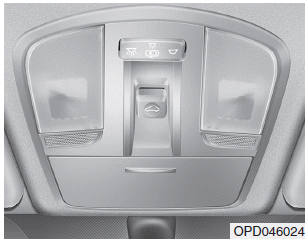
If your vehicle is equipped with a
sunroof, you can slide or tilt your
sunroof with the sunroof control lever
located on the overhead console.
The ignition switch must be in the ON
position before you can open or
close the sunroof.
The sunroof can be operated for
approximately 30 seconds after the
ignition key is removed or turned to
the ACC or LOCK(or OFF) position.
However, if the front door is opened,
the sunroof cannot be operated even
within 30 seconds.
read more


 Input Speed Sensor
 Shift Lever