Hyundai i-30: Rear Suspension System / Rear Coil Spring
Hyundai i30 (PD) 2018-2025 Service Manual / Suspension System (NON-ECS) / Rear Suspension System / Rear Coil Spring
Repair procedures
| Removal |
| 1. |
Loosen the wheel nuts slightly.
Raise the vehicle, and make sure it is securelysupported.
|
| 2. |
Remove the rear wheel and tire (A) from the rearhub.
|

| 3. |
Loosen the bolt & nut and then remove the rearshock absorber (A) from
the torsion beam axle.
|
| 4. |
Loosen the nut and then remove the rear stabilizerlink (A).
|
| 5. |
Loosen the bolt & nut and then remove the rear lowerarm from the rear
carrier.
|
| 6. |
Loosen the bolt & nut slightly and then pull the rearlower arm.
|
| 7. |
Remove the coil spring, upper pad, lower pad.
|
| 8. |
Installation in the reverse of removal.
|
| 9. |
Check the rear alignment.
(Refer to Tire/Wheels - "Alignment")
|
| Inspection |
| 1. |
Check the spring for distortion, aging or damage.
|
| 2. |
Check the spring upper pad and lower pad for aging or damage.
|
 Trailing Arm
Repair procedures
Removal
1.
Loosen the wheel nuts slightly.
Raise the vehicle, and make sure it is securelysupported...
 Rear Cross Member
Repair procedures
Removal
1.
Loosen the wheel nuts slightly.
Raise the vehicle, and make sure it is securelysupported...
Other information:
Hyundai i30 (PD) 2018-2025 Service Manual: Head Lamp Washer Motor
Repair procedures Removal Head Lamp Washer Motor • When servicing the washer pump, be careful not to damage the washer pump seal...
Hyundai i30 (PD) 2018-2025 Service Manual: Description and operation
Description The charging system includes a battery, an alternator with a built-in regulator, and the charging indicator light and wire. The Alternator has eight built-in diodes, each rectifying AC current to DC current. Therefore, DC current appears at alternator "B" terminal...
Categories
- Manuals Home
- 3rd Generation i30 Owners Manual
- 3rd Generation i30 Service Manual
- Recommended lubricants and capacities
- EPB malfunction indicator
- Brake/clutch fluid
- New on site
- Most important about car
Warning light and message
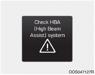
When the High Beam Assist (HBA)
System is not working properly, the
warning message will come on for a
few second. After the message disappears,
the master warning light ( )
will illuminate.
)
will illuminate.

Copyright © 2025 www.hi30.net