Hyundai i-30: Rear Suspension System / Rear Lower Arm
Hyundai i30 (PD) 2018-2025 Service Manual / Suspension System (NON-ECS) / Rear Suspension System / Rear Lower Arm
Repair procedures
| Removal |
| 1. |
Loosen the wheel nuts slightly.
Raise the vehicle, and make sure it is securelysupported.
|
| 2. |
Remove the rear wheel and tire (A) from the raerhub.
|

| 3. |
Loosen the bolt & nut and then remove the rearshock absorber (A) from
the torsion beam axle.
|
| 4. |
Loosen the nut and then remove the rear stabilizerlink (A).
|
| 5. |
Loosen the bolt & nut and then remove the rear lowerarm from the rear
arrier.
|
| 6. |
Loosen the bolt & nut and then remove the rear lowerarm from the rear
cross member.
|
| 7. |
Remove the stabilizer link from the rear lower arm.
|
| 8. |
Installation in the reverse of removal.
|
| 9. |
Check the alignment.
(Refer to Tires/Wheels - "Alignment")
|
| Inspection |
| 1. |
Check the bushing for wear and deterioration.
|
| 2. |
Check the rear lower arm for deformation.
|
| 3. |
Check for all bolts and nut.
|
| 4. |
Check the cracks or the cutting of the lower .
|
 Rear Upper Arm
Repair procedures
Removal
1.
Loosen the wheel nuts slightly.
Raise the vehicle, and make sure it is securelysupported...
 Rear Stabilizer Bar
Repair procedures
Removal
1.
Loosen the wheel nuts slightly.
Raise the vehicle, and make sure it is securelysupported...
Other information:
Hyundai i30 (PD) 2018-2025 Owner's Manual: Sensor to detect distance to the vehicle ahead
The Smart Cruise Control uses a sensor to detect distance to the vehicle ahead. Warning message SCC (Smart Cruise Control) disabled. Radar blocked When the sensor lens cover is blocked with dirt, snow, or debris, the Smart Cruise Control System operation may stop temporarily...
Hyundai i30 (PD) 2018-2025 Service Manual: Transmission Gear Oil
General information General Information 1. Check & Change intervals Check & Replenishmen Change Capacity Oil specification Normal Use Severe Use No check No service required 120000 km (80000 miles) 1...
Categories
- Manuals Home
- 3rd Generation i30 Owners Manual
- 3rd Generation i30 Service Manual
- Scheduled maintenance services
- To activate the ISG system
- Cruise control
- New on site
- Most important about car
Bonnet
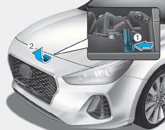
Opening the bonnet
1. Park the vehicle and set the parking brake.
2. Pull the release lever to unlatch the bonnet. The bonnet should pop open slightly.

Copyright © 2025 www.hi30.net