Hyundai i-30: Driver position memory system / Recalling memory positions
Hyundai i30 (PD) 2018-2025 Owner's Manual / Convenient features of your vehicle / Driver position memory system / Recalling memory positions
1. Move the shift lever into P (Park) whilst the ignition switch or the Engine Start/Stop button is in the ON position.
2. Press the desired memory button (1 or 2). The system will beep once, then the driver’s seat position, outside rearview mirror and instrument panel illumination will automatically adjust to the stored position (if equipped).
3. "Driver 1(or 2) settings is applied" will appear on the LCD display.
Information
- Whilst recalling the "1" memory position, pressing the SET or 1 button temporarily stops the adjustment of the recalled memory position. Pressing the 2 button recalls the "2" memory position.
- Whilst recalling the "2" memory position, pressing the SET or 2 button temporarily stops the adjustment of the recalled memory position. Pressing the 1 button recalls the "1" memory position.
- Whilst recalling the stored positions, pressing one of the control buttons for the driver's seat, outside rearview mirror, or instrument panel illumination will cause the movement of that component to stop and move in the direction that the control button is pressed.
 Storing memory positions
1. Move the shift lever into P (Park)
whilst the ignition switch or the
Engine Start/Stop button is in the
ON position.
2. Adjust the driver's seat position,
outside rearview mirror position
and instrument panel illumination
intensity to the desired position...
 Easy access function
The system will move the driver's
seat automatically as follows:
The shift lever is in P (Park)
• Without smart key system
- It will move the driver’s seat rearward
when the ignition key is
removed and the driver’s door is
opened...
Other information:
Hyundai i30 (PD) 2018-2025 Service Manual: Roof Side Molding
Repair procedures Replacement • Put on gloves to prevent hand injuries. • When removing with a flat-tip screwdriver or remover, wrap protective tape around the tools to prevent damage to components...
Hyundai i30 (PD) 2018-2025 Owner's Manual: Snow tyres
WARNING Snow tyres should be equivalent in size and type to the vehicle's standard tyres. Otherwise, the safety and handling of your vehicle may be adversely affected. We recommend you use snow tyres when road temperature is below 45°F (7°C)...
Categories
- Manuals Home
- 3rd Generation i30 Owners Manual
- 3rd Generation i30 Service Manual
- Scheduled maintenance services
- Engine coolant
- Light bulbs
- New on site
- Most important about car
Gauges and meters
Speedometer

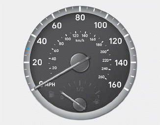
The speedometer indicates the speed of the vehicle and is calibrated in kilometers per hour (km/h) and/or miles per hour (MPH).
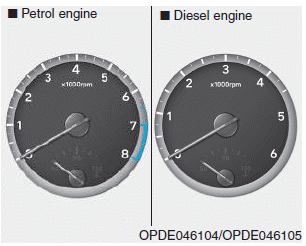
Tachometer

Copyright © 2025 www.hi30.net
