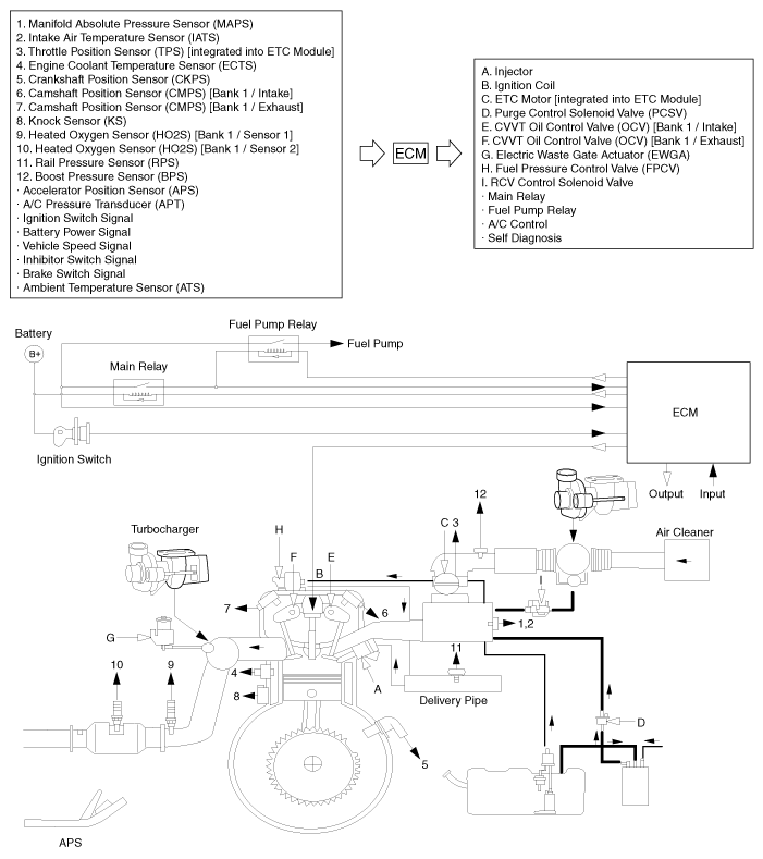
Hyundai i-30: Emission Control System / Schematic diagrams
Hyundai i30 (PD) 2018-2025 Service Manual / Emission Control System / Schematic diagrams
| Schematic Diagram |

 Components and components location
Components Location
1. PCV Valve
2. Canister
3. Purge control solenoid valve (PCSV)
4. Catalytic converter (WCC)
5...
Other information:
Hyundai i30 (PD) 2018-2025 Owner's Manual: Before driving
Before entering the vehicle Be sure all windows, outside mirror( s), and outside lights are clean and unobstructed. Remove frost, snow, or ice. Visually check the tyres for uneven wear and damage. Check under the vehicle for any sign of leaks...
Hyundai i30 (PD) 2018-2025 Owner's Manual: Engine compartment
1. Engine coolant reservoir/ Engine coolant cap 2.Brake/clutch fluid reservoir 3. Air cleaner 4. Engine oil dipstick 5. Engine oil filler cap 6.Windscreen washer fluid reservoir 7.Fuse box 8. Battery 1. Engine coolant reservoir 2...
Categories
- Manuals Home
- 3rd Generation i30 Owners Manual
- 3rd Generation i30 Service Manual
- Light bulbs
- Recommended lubricants and capacities
- Engine coolant
- New on site
- Most important about car
Warning light and message

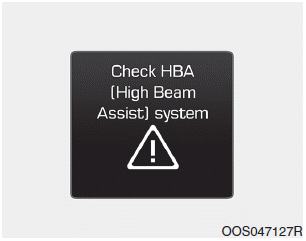
When the High Beam Assist (HBA)
System is not working properly, the
warning message will come on for a
few second. After the message disappears,
the master warning light ( )
will illuminate.
Copyright © 2025 www.hi30.net

