Hyundai i-30: Starting System / Starter
Description and operation
| Description |
The starting system includes the battery, starter, solenoid switch, ignition
switch, inhibitor switch, ignition lock switch, connection wires and the battery
cable.
When the ignition key is turned to the start position, current flows and energizes
the starter motor's solenoid coil.
The solenoid plunger and clutch shift lever are activated, and the clutch pinion
engages the ring gear.
The contacts close and the starter motor cranks.
In order to prevent damage caused by excessive rotation of the starter armature
when the engine starts, the clutch pinion gear overruns.
| 1. Solenoid 2. Brush assembly 3. Armature 4. Overrun clutch |
Specifications
| Specification |
Starter
▷ [ISG Type]
|
Item |
Specification |
|
|
Rated voltage |
12V, 1.2 kW |
|
|
The number of pinion teeth |
13 |
|
|
Performance |
Ampere |
Max. 90A |
|
[No-load, 11.5V] |
Speed |
Min. 3,500 rpm |
▷ [Non-ISG Type]
|
Item |
Specification |
|
|
Rated voltage |
12V, 0.9 kW |
|
|
The number of pinion teeth |
11 |
|
|
Performance [No-load, 11.5V] |
Ampere |
Max. 85A |
|
Speed |
Min. 3,300 rpm |
|
Schematic diagrams
| Circuit Diagram |
Repair procedures
| Removal |
| 1. |
Turn the ignition switch OFF and disconnect the battery (-) terminal.
|
| 2. |
Remove the engine room under cover.
(Refer to Engine Mechanical System - "Engine Room Under Cover")
|
| 3. |
Disconnect the starter ST connector (A).
|
| 4. |
Remove the stater "B" terminal cable mounting nut (A).
|
| 5. |
Remove the starter mounting bolts (A).
|
| 6. |
Remove the starter (A).
|
| Installation |
| 1. |
Install in the reverse order of removal.
|
| Disassembly |
| 1. |
Remove the M-terminal (A) on the magnetic switch assembly (B).
|
| 2. |
After loosening the screws (A), remove the magnetic switch assembly
(B).
|
| 3. |
Loosen the through bolts (A).
|
| 4. |
Remove the brush holder assembly (A), york assembly (B) and armature
assembly (C).
|
| 5. |
Remove the shield (A) and packing (B).
|
| 6. |
Remove the lever plate (A) and lever packing (B).
|
| 7. |
Remove the planet gear (A).
|
| 8. |
Remove the planet gear shaft assembly (A) and lever (B).
|
| 9. |
Press the stopper (A) using a socket (B).
|
| 10. |
Remove the stop ring (A) using the stop ring pliers (B).
|
| 11. |
Remove the stopper (A), overrunning clutch (B), internal gear (C) and
planet shaft (D).
|

| Reassembly |
| 1. |
Reassemble in the reverse order of disassembly.
|
| Inspection |
Starter Solenoid Inspection
| 1. |
Disconnect the lead wire from the M-terminal of solenoid switch.
|
| 2. |
Connect the battery as shown. If the starter pinion pops out, it is
working properly.
|
| 3. |
Disconnect the battery from the M terminal.
If the pinion does not retract, the hold-in coil is working properly.
|
| 4. |
Disconnect the battery also from the body. If the pinion retracts immediately,
it is working properly.
|
Free Running Inspection
| 1. |
Place the starter motor in a vise equipped with soft jaws and connect
a fully-charged 12-volt battery to starter motor as follows.
|
| 2. |
Connect a test ammeter (150-ampere scale) and carbon pile rheostats
shown is the illustration.
|
| 3. |
Connect a voltmeter (15-volt scale) across starter motor.
|
| 4. |
Rotate carbon pile to the off position.
|
| 5. |
Connect the battery cable from battery's negative post to the starter
motor body.
|
| 6. |
Adjust until battery voltage shown on the voltmeter reads 11.5 and 11
volts.
|
| 7. |
Confirm that the maximum amperage is within the specifications and that
the starter motor turns smoothly and freely.
|
Armature Inspection and Test
| 1. |
Remove the starter.
|
| 2. |
Disassemble the starter as shown at the beginning of this procedure.
|
| 3. |
Inspect the armature for wear or damage from contact with the permanent
magnet. If there is wear or damage, replace the armature.
|
| 4. |
Check the commutator (A) surface. If the surface is dirty or burnt,
resurface with emery cloth or a lathe within the following specifications,
or recondition with #500 or #600 sandpaper (B).
|
| 5. |
Measure the commutator (A) runout.
|
| 6. |
Check the mica depth (A). If the mica is too high (B), undercut the
mica with a hacksaw blade to the proper depth. Cut away all the mica
(C) between the commutator segments. The undercut should not be too
shallow, too narrow, or v-shaped (D).
|
| 7. |
Check for continuity between the segments of the commutator. If an open
circuit exists between any segments, replace the armature.
|
| 8. |
Check with an ohmmeter that no continuity exists between the commutator
(A) and armature coil core (B), and between the commutator and armature
shaft (C). If continuity exists, replace the armature.
|
Inspect Starter Brush
Any worn out or oil-soaked brushes should be replaced.
Starter Brush Holder Test
| 1. |
Check that there is no continuity between the (+) brush holder (A) and
(-) plate (B). If there is continuity, replace the brush holder assembly.
|
Inspect Overrunning Clutch
| 1. |
Slide the overrunning clutch along the shaft.
Replace if it does not slide smoothly.
|
| 2. |
Rotate the overrunning clutch both ways.
Does it lock in one direction and rotate smoothly in reverse? If it
does not lock in either direction or locks in both directions, replace
it.
|
| 3. |
If the starter drive gear is worn or damaged, replace the overrunning
clutch assembly. (The gear is not available separately.)
Check the condition of the flywheel or torque converter ring gear if
the starter drive gear teeth are damaged.
|
| Cleaning |
| 1. |
Do not immerse parts in cleaning solvent.
Immersing the yoke assembly and/or armature will damage the insulation
wipe these parts with a cloth only.
|
| 2. |
Do not immerse the drive unit in cleaning solvent.
The overrun clutch is pre-lubricated at the factory and solvent will
wash lubrication from the clutch.
|
| 3. |
The drive unit may be cleaned with a brush moistened with cleaning solvent
and wiped dry with a cloth.
|
 Troubleshooting
Troubleshooting
•
The battery must be in good condition and fully charged for
this troubleshooting...
 Starter Relay
Repair procedures
Inspection
1.
Turn ignition switch OFF and disconnect the battery negative (-) terminal.
2...
Other information:
Hyundai i30 (PD) 2018-2025 Service Manual: Head Lamps
Components and components location Components [Standard] 1. Low beam bulb 2. High beam bulb 3. Turn signal lamp 4. Dust cap 5. Static bending light (SBL) [LED] Description and operation LED Head Lamp 1...
Hyundai i30 (PD) 2018-2025 Owner's Manual: RCCW (Rear Cross-Traffic Collision Warning)
The Rear Cross-Traffic Collision warning function monitors approaching cross traffic from the left and right side of the vehicle when your vehicle is in reverse. Operating conditions To operate: Go to the 'User Settings → Driver Assistance and select Rear Cross- Traffic Collision warning' on the LCD display...
Categories
- Manuals Home
- 3rd Generation i30 Owners Manual
- 3rd Generation i30 Service Manual
- LKA system operation
- Drive mode integrated control system
- Brake/clutch fluid
- New on site
- Most important about car
Door locks
Operating door locks from outside the vehicle
Mechanical key
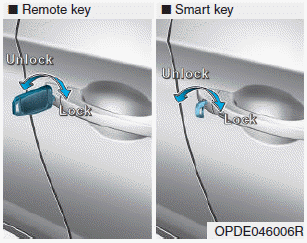
Turn the key toward the rear of the vehicle to unlock and toward the front of the vehicle to lock.
If you lock/unlock the driver's door with a key, a driver’s door will lock/unlock automatically.

Copyright © 2025 www.hi30.net