Hyundai i-30: Lighting System / Head Lamps
Components and components location
| Components |
[Standard]
| 1. Low beam bulb 2. High beam bulb 3. Turn signal lamp |
4. Dust cap 5. Static bending light (SBL) |
[LED]
Description and operation
| LED Head Lamp |
| 1. |
Static Bending Light (SBL)
|
Repair procedures
| Head Lamp Aiming Instructions |
| [Mechanical aiming] |
The head lamps should be aimed with the proper beam-setting equipment, and in
accordance with the equipment manufacturer's instructions.
|

Alternately turn the adjusting gear to adjust the head lamp aiming. If beam-setting
equipment is not available, proceed as follows :
| 1. |
Inflate the tires to the specified pressure and remove any loads from
the vehicle except the driver, spare tire, tools, coolant and fuel.
|
| 2. |
The vehicle should be placed on a flat ground.
|
| 3. |
Draw vertical lines (Vertical lines passing through respective head
lamp centers) and a horizontal line (Horizontal line passing through
center of head lamps) on the screen.
|
| 4. |
With the head lamp and battery in normal condition, aim the head lamps
so the brightest portion falls on the horizontal and vertical lines.
A : Horizontal (Low beam)
B : Vertical (Low beam)
C : Vertical (High beam)
D : Vertical (Low / High beam)
[Halogen]
[LED]
Front Fog Lamp Aiming
The front fog lamps should be aimed as the same manner of the head lamps
aiming.
With the front fog lamps and battery normal condition, aim the front
fog lamps by turning the adjusting screw (A) with a driver.
|
Head Lamp And Fog Lamp Aiming Point
| 1. |
Head Lamp (Low beam)
[LHD]
[RHD]
|
| 2. |
Head Lamp (High beam)
|
| 3. |
With the front fog lamp turned on, adjust the cut-off line to be located
as shown in the picture below.
|
Head lamp fogging
Check the below instruction procedure when the head lamp is fogged.
| Removal |
Head Lamp
| 1. |
Disconnect the negative (-) battery terminal.
|
| 2. |
Remove the front bumper cover.
(Refer to Body - "Front Bumper Cover")
|
| 3. |
Disconnect the head lamp connector (A).
|
| 4. |
Remove the head lamp (A) after loosening the mounting bolts.
|
| Replacement |
Turn signal lamp
| 1. |
Turn the head lamp power off.
|
| 2. |
Remove the bulb socket (B) and turn signal lamp bulb (A) from the lamp
assembly.
|
| 3. |
To install, reverse the removal procedure.
|
Bulb (Low Beam)
| 1. |
Turn the head lamp power off.
|
| 2. |
Remove the bulb caps from the head lamp assembly after turning in the
counter clock-wise direction.
|
| 3. |
Remove the head lamp low beam bulb (C) after removing the socket (B)
from the head lamp assembly.
|
| 4. |
To install, reverse the removal procedure.
|
Bulb (High Beam)
| 1. |
Turn the head lamp power off.
|
| 2. |
Remove the bulb caps from the head lamp assembly after turning in the
counter clock-wise direction.
|
| 3. |
Remove the head lamp high beam bulb (A) after disengaing the retaining
clip (B) and disconnect the lamp connector.
|
| 4. |
To install, reverse the removal procedure.
|
| Installation |
| 1. |
Install the head lamp assembly after connecting the connector.
|
| 2. |
Install the front bumper cover.
|
| 3. |
Connect the negative (-) battery terminal.
|
 Components and components location
Component Location
1. Head lamp
(Low)
2. Head lamp (High)
3. Position lamp
4. Turn signal lamp & Position lamp & daytime Running light (DRL)
5...
 Room Lamp
Repair procedures
Removal
Room lamp (Normal roof)
1.
Disconnect the negative (-) battery terminal.
2...
Other information:
Hyundai i30 (PD) 2018-2025 Owner's Manual: Fuel filter (for diesel)
Draining water from fuel filter The fuel filter in the diesel engine operates the critical function of separating water from the fuels and preventing accumulating of water in the base. When enough water is accumulated inside the fuel filter, the warning light () illuminates with the ignition switch in the ON position...
Hyundai i30 (PD) 2018-2025 Owner's Manual: Electronic Parking Brake (EPB)
Applying the parking brake To apply the EPB (Electronic Parking Brake): 1. Depress the brake pedal. 2. Pull up the EPB switch. Make sure the Parking Brake Warning Light comes on. WARNING To reduce the risk of SERIOUS INJURY or DEATH, do not operate the EPB whilst the vehicle is moving except in an emergency situation...
Categories
- Manuals Home
- 3rd Generation i30 Owners Manual
- 3rd Generation i30 Service Manual
- Cruise control
- Engine compartment
- FCA sensor
- New on site
- Most important about car
Air bag - supplemental restraint system
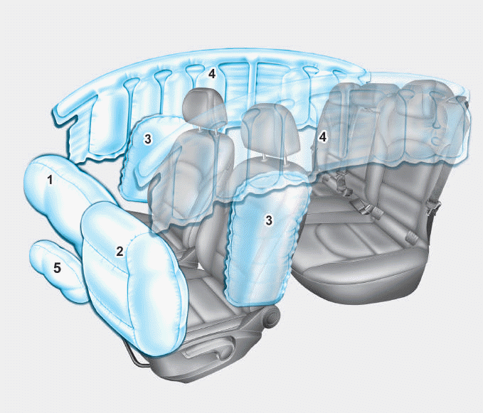
1. Driver’s front air bag
2. Passenger’s front air bag
3. Side air bag*
4. Curtain air bag*
5. Knee air bag*
6. Front passenger air bag ON/OFF
switch

Copyright © 2025 www.hi30.net