Hyundai i-30: Cylinder Block / Cylinder Block
Hyundai i30 (PD) 2018-2025 Service Manual / Engine Mechanical System / Cylinder Block / Cylinder Block
Repair procedures
| Disassembly |
|

|

| 1. |
Remove the engine assembly from the vehicle.
(Refer to Engine and Transaxle Assembly - "Engine and Transaxle Assembly")
|
| 2. |
Remove the transaxle assembly from the engine assembly.
(Refer to Double Clutch Transmission (DCT) System - "Double Clutch Transmission
(DCT)")
|
| 3. |
Remove the flywheel.
(Refer to Cylinder Block - "Flywheel")
|
| 4. |
Remove the rear oil seal.
(Refer to Cylinder Block - "Rear Oil Seal")
|
| 5. |
Install the engine to engine stand for disassembly.
|
| 6. |
Remove the timing chain.
(Refer to Timing System - "Timing Chain")
|
| 7. |
Remove the intake manifold.
(Refer to Intake and Exhaust System - "Intake Manifold")
|
| 8. |
Remove the exhaust manifold.
(Refer to Intake and Exhaust System - "Exhayst Manifold")
|
| 9. |
Remove the cylinder head assembly.
(Refer to Cylinder Head Assembly - "Cylinder Head")
|
| 10. |
Remove the A/C compressor.
(Refer to Heating, Ventilation Air conditioning - "Compressor")
|
| 11. |
Remove the inlet fitting.
(Refer to Cooling System - "Inlet Fitting")
|
| 12. |
Remove the knock sensor.
(Refer to Engine Control / Fuel System - "Knock Sensor")
|
| 13. |
Remove the oil pump.
(Refer to Lubrication System - "Oil Pump")
|
| 14. |
Remove the ladder frame (A).
Insert the blade of SST (09215-3C000) between the cylinder block and
the ladder frame and cut out applied sealer. Then, remove the ladder
frame.
|
| 15. |
Remove the piston and connecting rod assemblies.
(Refer to Cylinder Block - "Piston and Connecting Rod")
|
| 16. |
Remove the crankshaft.
(Refer to Cylinder Block - "Crankshaft")
|
| 17. |
Remove the water jacket seperator.
(Refer to Cylinder Block - "Water Jacket Seperator")
|
| 18. |
Remove the piston cooling jet (A).
|
| Inspection |
Cylinder Block
| 1. |
Remove the gasket material.
Using a gasket scraper, remove all the gasket material from the top
surface of the cylinder block.
|
| 2. |
Clean the cylinder block.
Using a soft brush and solvent, thoroughly clean the cylinder block.
|
| 3. |
Inspect the top surface of the cylinder block for flatness.
Using a precision straight edge and feeler gauge, measure the surface
contacting the cylinder head gasket for warpage.
|
| 4. |
Inspect the cylinder bore.
Visually check the cylinder for vertical scratchs.
If deep scratchs are present, replace the cylinder block.
|
| 5. |
Inspect the cylinder bore diameter.
Using a cylinder bore gauge, measure the cylinder bore diameter at position
in the thrust and axial direction.
|
| 6. |
Check the cylinder bore size code on the cylinder block.
Discrimination of cylinder bore size
|
| Reassembly |
|
| 1. |
Install the piston cooling jet (A).
|
| 2. |
Install the water jacket seperator.
(Refer to Cylinder Block - "Water Jacket Seperator")
|
| 3. |
Install the crankshaft.
(Refer to Cylinder Block - "Crankshaft")
|
| 4. |
Install the piston and connecting rod assemblies.
(Refer to Cylinder Block - "Piston and Connecting Rod")
|
| 5. |
Install the ladder frame
|
| 6. |
Assemble the other parts in the reverse order of disassembly.
|
 Crankshaft
Components and components location
Components
1. Thrust bearing
2. Upper main bearing
3. Crankshaft
4. Lower main
bearing
5...

Other information:
Hyundai i30 (PD) 2018-2025 Service Manual: Repair procedures
Removal [Manual Transaxle Type] 1. Turn ignition switch OFF and disconnect the negative (-) battery cable. 2. Remove the clutch master cylinder. (Refer to Clutch System - "Cluch Master Cylinder") 3...
Hyundai i30 (PD) 2018-2025 Owner's Manual: Power window lock switch
The driver can disable the power window switches on the rear passengers' doors by pressing the power window lock switch. When the power window lock switch is pressed: The driver's master control can operate all the power windows. The front passenger's control can operate the front passenger's power window...
Categories
- Manuals Home
- 3rd Generation i30 Owners Manual
- 3rd Generation i30 Service Manual
- Tyre pressure monitoring system
- EPB malfunction indicator
- Scheduled maintenance services
- New on site
- Most important about car
Air bag - supplemental restraint system
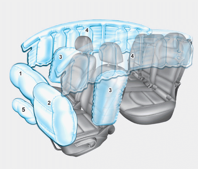
1. Driver’s front air bag
2. Passenger’s front air bag
3. Side air bag*
4. Curtain air bag*
5. Knee air bag*
6. Front passenger air bag ON/OFF
switch

Copyright © 2025 www.hi30.net