Hyundai i-30: Crash Pad / Crash Pad Side Cover
Hyundai i30 (PD) 2018-2025 Service Manual / Body (Interior and Exterior) / Crash Pad / Crash Pad Side Cover
Components and components location
| Component Location |
| [LH] |
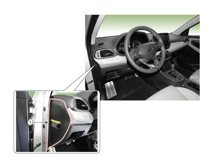
| 1. Crash pad
side cover [LH] |
| [RH] |
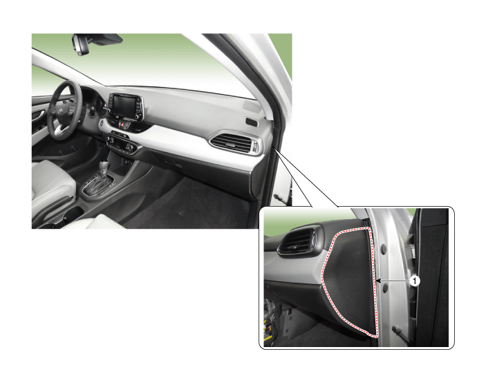
| 1. Crash pad
side cover [RH] |
Repair procedures
| Replacement |
|
|
| 1. |
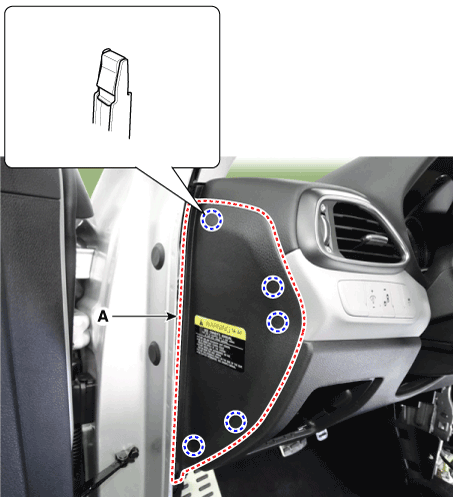
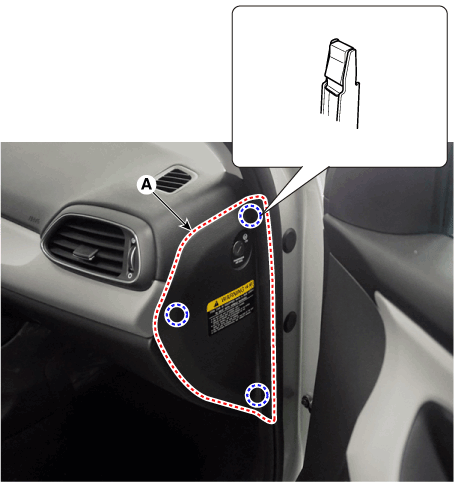
Using a screwdriver or remover, remove the crash pad side cover (A).
[LH]
[RH]
|
| 2. |
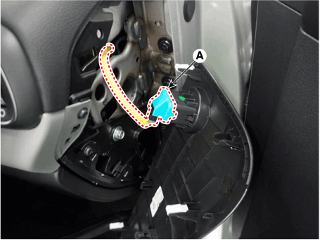
Press the lock pin and separate the connector (A). [RH]
|
| 3. |
To install, reverse removal procedure.
|
 Steering Column Shroud Panel
Components and components location
Component Location
1. Steering column
shroud lower panel
2. Steering column
shroud upper panel
Repair procedures
Replacement
[Steering column shroud upper panel]
•
Put on gloves to prevent hand injuries...
 Crash Pad Under Cover
Repair procedures
Replacement
•
Put on gloves to prevent hand injuries...
Other information:
Hyundai i30 (PD) 2018-2025 Service Manual: Engine Room Under Cover
Repair procedures Removal and installation 1. Remove the engine room under cover (A). Tightening torque : 3.9 - 5.9 N.m (0.4 - 0.6 kgf.m, 2.9 - 4.3 lb-ft) 2...
Hyundai i30 (PD) 2018-2025 Owner's Manual: Exhaust emission control system
The Exhaust Emission Control System is a highly effective system which controls exhaust emissions whilst maintaining good vehicle performance. Vehicle modifications This vehicle should not be modified. Modification of your vehicle could affect its performance, safety or durability and may even violate governmental safety and emissions regulations...
Categories
- Manuals Home
- 3rd Generation i30 Owners Manual
- 3rd Generation i30 Service Manual
- FCA sensor
- Scheduled maintenance services
- Exhaust System (DPF) Warning Light. Glow Indicator Light
- New on site
- Most important about car
Seat belt warning light
Seat belt warning
Driver’s seat belt warning
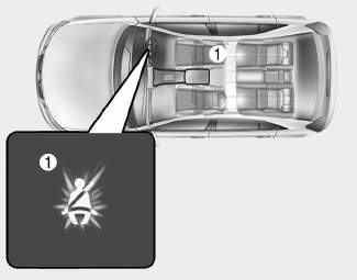
■ Instrument cluster
As a reminder to the driver, the seat belt warning light will illuminate for approximately 6 seconds each time you turn the ignition switch ON regardless of belt fastening.
Copyright © 2025 www.hi30.net


