Hyundai i-30: Cylinder Head Assembly / CVVT & Camshaft

Hyundai i30 (PD) 2018-2024 Service Manual / Engine Mechanical System / Cylinder Head Assembly / CVVT & Camshaft

Description and operation
Description
The continuous variable valve timing (CVVT) system advances or retards the opening of an intake or exhaust valve according to the ECM signals that are determined based on engine RPM and load.
Due to CVVT control, a valve overlap or underlap occurs between the intake valve and exhaust valve, resulting in the reduction of pumping loss, recirculation of exhaust gas, improvement in combustion stability and volumetric efficiency, and increase in expansion work. This in turn improves fuel efficiency and engine performance and reduces emission gases (NOx and HC).
The CVVT system is composed of a CVVT oil control valve (OCV), CVVT oil temperature sensor (OTS), and a cam phaser; The OCV receives a pulse width modulation signal from the ECM and controls the flow of oil to supply oil to the cam phaser, the OTS measures the temperature of the engine oil, and the cam phaser changes the phase of the camshaft using the engine oil pressure.
The oil supplied from the CVVT OCV rotates the rotor connected to the camshaft inside the cam phaser. The rotor, in turn, rotates the camshaft in the direction of engine rotation (intake advanced / exhaust retarded) or in the opposite direction of engine rotation (intake retarded / exhaust advanced) to change the phase angle of the cam.

Operation Principle
The CVVT has the mechanism rotating the rotor vane with hydraulic force generated by the engine oil supplied to the advance or retard chamber in accordance with the CVVT oil control valve control.
  
A separate solenoid valve is installed on the chain cover in the intake side for closing and releasing a separate lock pin.
1.
Intake CVVT

2.
Exhaust CVVT

[CVVT System Mode]

(1) Low Speed / Low Load
(2) Part Load


(3) Low Speed / High Load
(4) High Speed / High Load


Driving
Condition
Exhaust Valve
Intake Valve
Valve
Timing
Effect
Valve
Timing
Effect
(1) Low Speed
/Low Load
Completely
Advance
* Valve Under-lap
* Improvement of combustion stability
Middle
* Valve Under-lap
* Improvement of combustion stability
(2) Part Load
Retard
* Reduction of HC
Retard
* Delays the closing time of intake valve to reduce pumping loss
(3) Low Speed
/High Load
Completely Advance
* Reduction of pumping loss
Advance
* Improvement of volumetric efficiency
(4) High Speed
/High Load
Completely Advance
* Reduction of pumping loss
Advance
* Improvement of volumetric efficiency

Repair procedures
Removal
  
Use fender covers to avoid damaging painted surfaces.
To avoid damage, unplug the wiring connectors carefully while holding the connector portion.
  
Mark all wiring and hoses to avoid misconnection.
Turn the crankshaft pulley so that the No. 1 piston is at top dead center.
1.
Remove the cylinder head cover.
(Refer to Cylinder Head Assembly - "Cylinder Head Cover")
2.
Turn the crankshaft damper pulley and align its groove with the timing mark of the timing chain cover to set the piston of No.1 cylinder to the top dead center on compression stroke.

3.
Remove the timing chain cover.
(Refer to Timing System - "Timing Chain Cover")
4.
Before removing the timing chain, mark the timing chain with an identification based on the location of the sprocket (CVVT) because the identification mark on the chain for TDC (Top Dead Center) can be erased.

5.
Remove the timing chain.
(Refer to Timing System - "Timing Chain")
6.
Remove the intake CVVT assembly (A) and exhaust CVVT assembly (B).

  
To prevent impurities from entering OCV & center bolt.
Do not use any dropped OCV & center bolt.
When removing and installing the intake/exhaust OCV & Center bolt, hold the camshaft with a wrench to prevent the camshaft from rotating.
7.
Remove the front camshaft bearing cap (A) and the camshaft bearing caps (B).

8.
Remove the CVVD assembly.
  
After removing the CVVD unit, make sure that the parts such as lifter, cam, etc are not separated.
Ensure that the CVVD components are not damaged.
Use the CVVD fixture
(1)
Install the CVVD fixture (A) over the CVVD assembly.

(2)
Remove the CVVD assembly.

Do not use the CVVD fixture
(1)
Remove the CVVD assembly.

9.
Remove the exhaust camshaft (A).

Inspection
Camshaft
1.
Inspect the cam lobes.
Using a micrometer, measure the cam lobe height.
Cam height
Intake : 36.125 mm (1.4222 in.)
Exhaust : 35.73 mm (1.4067 in)

If the cam lobe height is less than standard, replace the camshaft.
2.
Check the surface of the camshaft journal for wear.
If the journal is worn excessively, replace the camshaft.
3.
Inspect the camshaft journal clearance.
(1)
Clean the bearing caps and camshaft journals.
(2)
Place the camshafts on the cylinder head.
(3)
Lay a strip of plastigage across each of the camshaft journals.

(4)
Install the front camshaft bearing cap and the camshaft bearing caps as following method with specified torque.
Tightening torque
A(M8) : 18.6 - 22.6 N.m (1.9 - 2.3 kgf.m, 13.7 - 16.6 lb-ft)
B(M6) : 11.7 - 13.7 N.m (1.2 -1.4 kgf.m, 8.6 - 10.1 IB-ft)

  
Do not turn the camshaft.
When cam caps are installed, the arrows on top of caps must point outward from the engine.
(5)
Remove the bearing caps.
(6)
Measure the plastigage at its widest point.
Bearing oil clearance
Standard
Intake :
0.032 - 0.062 mm (0.0013 - 0.0024 in) (No.1,2,3,4,5 journal)
Exhaust :
0.032 - 0.062 mm (0.0013 - 0.0024 in) (No.1,2,3,4,5 journal)
If the oil clearance is greater than maximum, replace the camshaft. If necessary, replace cylinder head.

(7)
Completely remove the plastigage.
(8)
Remove the camshafts.
4.
Inspect the camshaft end play.
(1)
Install the camshafts.

(2)
Install the front camshaft bearing cap and the camshaft bearing caps as following method with specified torque.
Tightening torque
A(M8) : 18.6 - 22.6 N.m (1.9 - 2.3 kgf.m, 13.7 - 16.6 lb-ft)
B(M6) : 11.7 - 13.7 N.m (1.2 -1.4 kgf.m, 8.6 - 10.1 IB-ft)

  
Do not turn the camshaft.
When cam caps are installed, arrows on the top of caps must point to out side of engine.
(3)
Using a dial indicator, measure the end play while moving the camshaft back and forth.
Camshaft end play
Intake : 0.1 - 0.2 mm (0.0039 - 0.0078 in)
Exhaust : 0.1 - 0.2 mm (0.0039 - 0.0078 in)

If the end play is greater than maximum, replace the camshaft. If necessary, replace cylinder head.
(4)
Remove the camshafts.
Installation
1.
Install the exhaust camshaft (A).

2.
Install the CVVD assembly (A).

  
After installing the CVVD, check whether the swing arm is separated or is installed correctly.
When installing the intake camshaft, spray the engine oil to the camshaft journal installing part (A) of the cam carrier.
The amount of application should be enough to flow down both the front and back sides when it is applied to the center.
For installation, the timing mark (A) of the intake CVVT and the timing chain mark (B) should be matched.

  
During the installation, there should be no artifical rotation or movement of the guide bracket and control shaft.
When removing the CVVD fixing jig, be sure to securely tighten the M6 bolts.
If CVVD fixing jig is available, be sure to work by using it.
Use the CVVD fixture
1)
When installing the CVVD assembly mounting bolts (M6), tighten sequence shown.
Tightening torque :
1ST
4.9 - 6.9 N.m (0.5 - 0.7 kgf.m, 3.6 - 5.1 lb-ft)
2nd
9.8 - 11.8 N.m (1.0 - 1.2 kgf.m, 7.2 - 8.7 lb-ft)

2)
Remove the CVVD fixture (A).

3)
Tighten the CVVD assembly mounting bolts (M8) according to the tightening sequence shown below.
Tightening torque :
9.8 - 11.8 N.m (1.0 - 1.2 kgf.m, 7.2 - 8.7 lb-ft)

4)
Remove the CVVD assembly mounting bolts (M6) (A).

5)
Tighten the CVVD assembly mounting bolts (M6) according to the tightening sequence shown below.
Tightening torque :
4.9 - 6.9 N.m (0.5 - 0.7 kgf.m, 3.6 - 5.1 lb-ft)

6)
Tighten the CVVD assembly mounting bolts (M8) according to the tightening sequence shown below.
Tightening torque :
18.6 - 22.6 N.m (1.9 - 2.3 kgf.m, 13.7 - 16.6 lb-ft)

7)
Tighten the CVVD assembly mounting bolts (M6) according to the tightening sequence shown below.
Tightening torque :
9.8 - 11.8 N.m (1.0 - 1.2 kgf.m, 7.2 - 8.7 lb-ft)

8)
Measure the clearance between the control shaft bearing cap and the end of control shaft using a clearance gauge.
Clearance : 0.0 - 0.05 mm (0.0 - 0.002 in.)

Do not use the CVVD fixture
1)
Tighten the CVVD assembly mounting bolts (M6) according to the tightening sequence shown below.
Tightening torque :
4.9 - 6.9 N.m (0.5 - 0.7 kgf.m, 3.6 - 5.1 lb-ft)

2)
Tighten the CVVD assembly mounting bolts (M8) according to the tightening sequence shown below.
Tightening torque :
9.8 - 11.8 N.m (1.0 - 1.2 kgf.m, 7.2 - 8.7 lb-ft)

3)
Tighten the CVVD assembly mounting bolts (M8) according to the tightening sequence shown below.
Tightening torque :
18.6 - 22.6 N.m (1.9 - 2.3 kgf.m, 13.7 - 16.6 lb-ft)

4)
Tighten the CVVD assembly mounting bolts (M6) according to the tightening sequence shown below.
Tightening torque :
9.8 - 11.8 N.m (1.0 - 1.2 kgf.m, 7.2 - 8.7 lb-ft)

5)
Release the torque of control shaft bearing cap bolt (A).

6)
Push the control shaft bearing cap as close as possible in the direction of the arrow.

7)
Install the control shaft bearing cap mounting bolts (A).
Tightening torque :
9.8 - 11.8 N.m (1.0 - 1.2 kgf.m, 7.2 - 8.7 lb-ft)

8)
Measure the clearance between the control shaft bearing cap and the end of control shaft using a clearance gauge.
Clearance : 0.0 - 0.05 mm (0.0 - 0.002 in.)

3.
Install the intake CVVT assembly (A) and exhaust CVVT assembly (B).
Tightening torque :
Intake : 22.5 - 26.4 N.m (2.3 - 2.7 kgf.m, 16.6 - 19.5 lb-ft) + 28 - 32°
Exhaust : 22.5 - 26.4 N.m (2.3 - 2.7 kgf.m, 16.6 - 19.5 lb-ft) + 32 - 36°

  
To prevent impurities from entering OCV & center bolt.
Do not use any dropped OCV & center bolt.
When removing and installing the intake/exhaust OCV & Center bolt, hold the camshaft with a wrench to prevent the camshaft from rotating.
When installing OCV & center bolt, temporarily install by hand, and then fully install by using a tool.
When installing OCV & center bolt, install to the specified tightening torque.
When installing OCV & center bolt, use the hand operated tool and do not use the power tool or air tool to prevent the part from getting damaged.
4.
Install the front camshaft bearing cap and the camshaft bearing caps as following method with specified torque.
Tightening torque :
A(M8) : 18.6 - 22.6 N.m (1.9 - 2.3 kgf.m, 13.7 - 16.6 lb-ft)
B(M6) : 11.7 - 13.7 N.m (1.2 -1.4 kgf.m, 8.6 - 10.1 IB-ft)

5.
Install the other parts in the reverse order of removal.

    Cylinder Head Cover

    Components and components location Components 1. Cylinder head cover 2. Engine oil cap 3. Cylider head cover gasket 4...

    CVVD Assembly

    Description and operation Description CVVD (Continuous Variable Valve Duration) System is a device to control the optimum open and close timing according to the driving mode by changing the valve opening section...

    Other information:

    Hyundai i30 (PD) 2018-2024 Owner's Manual: Fuel filter (for diesel)


    Draining water from fuel filter The fuel filter in the diesel engine operates the critical function of separating water from the fuels and preventing accumulating of water in the base. When enough water is accumulated inside the fuel filter, the warning light () illuminates with the ignition switch in the ON position...

    Hyundai i30 (PD) 2018-2024 Service Manual: Components and components location


    ..

    Categories

    Door locks

    Operating door locks from outside the vehicle

    Mechanical key

    Hyundai i30. Door locks

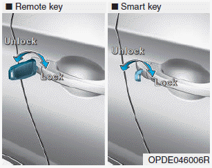
    Turn the key toward the rear of the vehicle to unlock and toward the front of the vehicle to lock.

    If you lock/unlock the driver's door with a key, a driver’s door will lock/unlock automatically.

    read more


    Copyright © 2024 www.hi30.net