Hyundai i-30: Cylinder Head Assembly / Cylinder Head Cover
Hyundai i30 (PD) 2018-2025 Service Manual / Engine Mechanical System / Cylinder Head Assembly / Cylinder Head Cover
Components and components location
| Components |
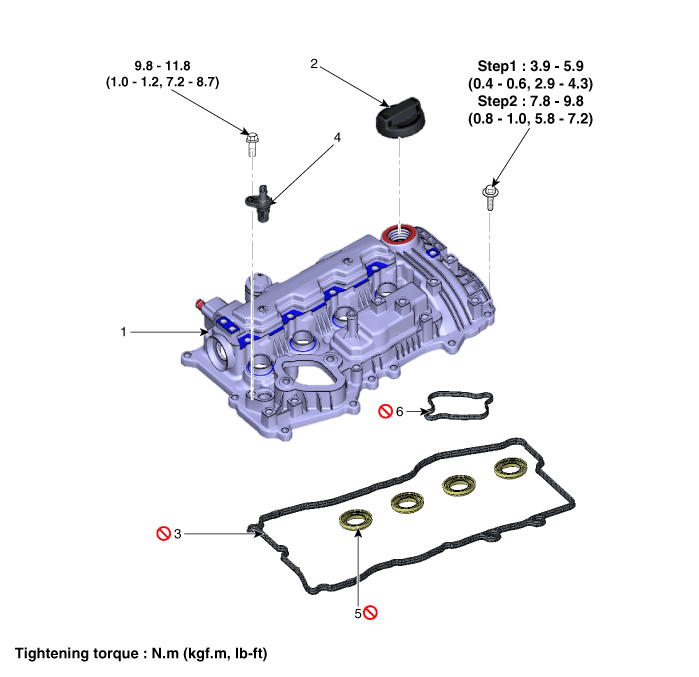
| 1. Cylinder head
cover 2. Engine oil cap 3. Cylider head cover gasket |
4. Camshaft position
sensor 5. Cylider head cover oil seal 6. High pressure fuel pump gasket |
Repair procedures
| Removal |
|
|
| 1. |
Disconnect the battery negative terminal.
|
| 2. |
Remove the engine cover.
(Refer to Engine and Transaxle Assembly - "Engine Cover")
|
| 3. |
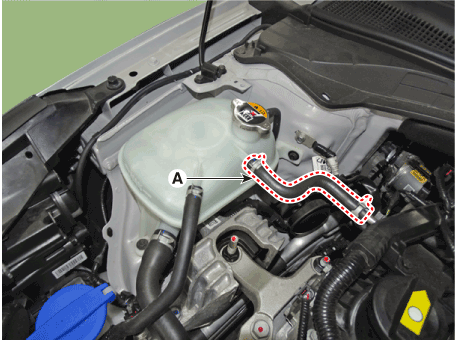
Disconnect the reservoir tank water hose (A).
|
| 4. |
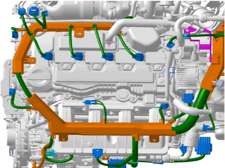
Disconnect the wiring connectors and harness clamps and remove the connector
brackets around the cylinder head cover.
|
| 5. |
Remove the air duct and air cleaner assembly.
(Refer to Intake and Exhasut System - "Air Cleaner")
|
| 6. |
Remove the high pressure fuel pump.
(Refer to Engine Control/Fuel System - "High Pressure Fuel Pump")
|
| 7. |
Remove the ignition coils.
(Refer to Engine Electrical System - "Ignition Coil")
|
| 8. |
Remove the CVVD acuator.
|
| 9. |
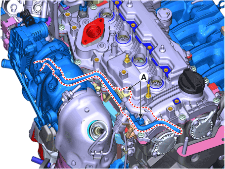
Remove the turbocharger water pipe (A).
|
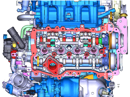
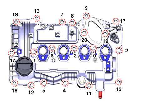
| 10. |
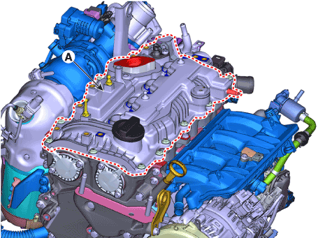
Remove the cylinder head cover (A).
|
| Installation |
| 1. |
Install the cylinder head cover (A).
|
| 2. |
Install the other parts in the reverse order of removal.
|
 Components and components location
Components
1. Camshaft
bearing cap
2. Exhaust camshaft bearing cap
3. Front camshaft bearing cap
4. Exhaust camshaft
5...
 CVVT & Camshaft
Description and operation
Description
The continuous variable valve timing (CVVT) system advances or retards the opening
of an intake or exhaust valve according to the ECM signals that are determined
based on engine RPM and load...
Other information:
Hyundai i30 (PD) 2018-2025 Service Manual: Components and components location
..
Hyundai i30 (PD) 2018-2025 Service Manual: Dynamic Damper
Components and components location Components 1. BJ assembly 2. BJ circlip 3. BJ boot band 4. BJ boot 5. Dynamic damper band 6. Dynamic damper 7. Shaft 8. TJ boot band 9. TJ boot 10...
Categories
- Manuals Home
- 3rd Generation i30 Owners Manual
- 3rd Generation i30 Service Manual
- Battery replacement
- Scheduled maintenance services
- Exhaust System (DPF) Warning Light. Glow Indicator Light
- New on site
- Most important about car
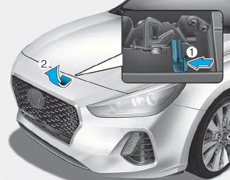
Bonnet
Opening the bonnet
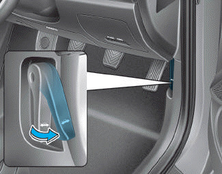
1. Park the vehicle and set the parking brake.
2. Pull the release lever to unlatch the bonnet. The bonnet should pop open slightly.
Copyright © 2025 www.hi30.net


