Hyundai i-30: Engine Control System / Description and operation
Hyundai i30 (PD) 2018-2025 Service Manual / Engine Control / Fuel System / Engine Control System / Description and operation
| Description |
If the Gasoline Engine Control system components (sensors, ECM, injector, etc.)
fail, interruption to the fuel supply or failure to supply the proper amount
of fuel for various engine operating conditions will result. The following situations
may be encountered.
| 1. |
Engine is hard to start or does not start at all.
|
| 2. |
Unstable idle.
|
| 3. |
Poor driveability
|
If any of the above conditions are noted, first perform a routine diagnosis
that includes basic engine checks (ignition system malfunction, incorrect engine
adjustment, etc.). Then, inspect the Gasoline Engine Control system components
with the diagnostic tool.
|

Malfunction Indicator Lamp (MIL)
| [EOBD] |
A malfunction indicator lamp illuminates to notify the driver that there is
a problem with the vehicle. However, the MIL will go off automatically after
3 subsequent sequential driving cycles without the same malfunction. Immediately
after the ignition switch is turned on (ON position - do not start), the MIL
will illuminate continuously to indicate that the MIL operates normally.
Faults with the following items will illuminate the MIL.
| • |
Catalyst
|
| • |
Fuel system
|
| • |
Mass Air Flow Sensor (MAFS)
|
| • |
Intake Air Temperature Sensor (IATS)
|
| • |
Engine Coolant Temperature Sensor (ECTS)
|
| • |
Throttle Position Sensor (TPS)
|
| • |
Upstream Oxygen Sensor
|
| • |
Upstream Oxygen Sensor Heater
|
| • |
Downstream Oxygen Sensor
|
| • |
Downstream Oxygen Sensor Heater
|
| • |
Injector
|
| • |
Misfire
|
| • |
Crankshaft Position Sensor (CKPS)
|
| • |
Camshaft Position Sensor (CMPS)
|
| • |
Evaporative Emission Control System
|
| • |
Vehicle Speed Sensor (VSS)
|
| • |
Idle Speed Control Actuator (ISCA)
|
| • |
Power Supply
|
| • |
ECM/ PCM
|
| • |
MT/AT Encoding
|
| • |
Acceleration Sensor
|
| • |
MIL-on Request Signal
|
| • |
Power Stage
|
|
| [NON-EOBD] |
A malfunction indicator lamp illuminates to notify the driver that there is
a problem with the vehicle. However, the MIL will go off automatically after
3 subsequent sequential driving cycles without the same malfunction. Immediately
after the ignition switch is turned on (ON position - do not start), the MIL
will illuminate continuously to indicate that the MIL operates normally.
Faults with the following items will illuminate the MIL
| • |
Heated oxygen sensor (HO2S)
|
| • |
Mass Air Flow sensor (MAFS)
|
| • |
Throttle position sensor (TPS)
|
| • |
Engine coolant temperature sensor (ECTS)
|
| • |
Idle speed control actuator (ISCA)
|
| • |
Injectors
|
| • |
ECM
|
|
| [INSPECTION] |
| 1. |
After turning ON the ignition key, ensure that the light illuminates
for about 5 seconds and then goes out.
|
| 2. |
If the light does not illuminate, check for an open circuit in the harness,
a blown fuse or a blown bulb.
|
Self-Diagnosis
The ECM monitors the input/output signals (some signals at all times and the
others under specified conditions). When the ECM detects an irregularity, it
records the diagnostic trouble code, and outputs the signal to the Data Link
connector. The diagnosis results can be read with the MIL or the diagnostic
tool. Diagnostic Trouble Codes (DTC) will remain in the ECM as long as battery
power is maintained. The diagnostic trouble codes will, however, be erased when
the battery terminal or ECM connector is disconnected, or by the diagnostic
tool.
|
The Relation Between DTC and Driving Pattern in EOBD System
| 1. |
When the same malfunction is detected and maintained during two sequential
driving cycles, the MIL will automatically illuminate.
|
| 2. |
The MIL will go off automatically if no fault is detected after 3 sequential
driving cycles.
|
| 3. |
A Diagnostic Trouble Code (DTC) is recorded in ECM memory when a malfunction
is detected after two sequential driving cycles. The MIL will illuminate
when the malfunction is detected on the second driving cycle.
If a misfire is detected, a DTC will be recorded, and the MIL will illuminate,
immediately after a fault is first detected.
|
| 4. |
A Diagnostic Trouble Code (DTC) will automatically erase from ECM memory
if the same malfunction is not detected for 40 driving cycles.
|
 Components and components location
Components Location
1. ECM (Engine
Control Module)
2. Mass Air Flow Sensor (MAFS)
3. Manifold Absolute Pressure Sensor (MAPS)
4...
 Engine Control Module (ECM)
Schematic diagrams
ECM Terminal and Input /
Output signal
ECM Harness Connector
ECM Terminal Function
Connector [A]
Terminal
Description
1
Fuel Pressure Regulator Valve (FPRV) [High] Control
2
Integrated Thermal Management Module (ITM) Motor (+)
3
Integrated Thermal Management Module (ITM) Motor (-)
4
Exhaust Gas Temperature Sensor (EGTS) #2 (T4) Ground [GPF Type]
5
Engine Coolant Temperature Sensor (ECTS) #1 Ground
6
-
7
Engine Coolant Temperature Sensor (ECTS) #2 Ground
8
Differential Pressure Valve (DPV) Ground
9
Rail Pressure Sensor (RPS) Ground
10
Exhaust Gas Temperature Sensor (EGTS) Ground
11
Manifold Absolute Pressure Sensor (MAPS) Ground
12
Electric Waste Gate Control Actuator (EWGA) Ground
13
EGR Pressure Sensor Ground
14
Oil Pressure & Temperature Sensors (OPTS) Ground
15
Electric Exhaust Gas Recirculation (EEGR) Control Valve Ground
16
-
17
A/C Pressure Transducer (APT) Ground
18
Sensor Power (+5V) (Camshaft Position Sensor (CMPS) [Bank 1 / Intake, Exhaust])
19
Sensor Power (+5V) (Manifold Absolute Pressure Sensor (MAPS))
Sensor Power (+5V) (Electric Exhaust Gas Recirculation (EEGR))
Sensor Power (+5V) (Crankshaft Position Sensor (CKPS))
20
Sensor Power (+5V) (Oil Pressure & Temperature Sensors (OPTS))
Sensor Power (+5V) (Electric Throttle Control Module (ETC))
Sensor Power (+5V) (Rail Pressure Sensor (RPS))
21
Throttle Position Sensor (TPS) Ground
22
Electric Exhaust Gas Recirculation (EEGR) Control Valve Motor (+)
23
Electric Exhaust Gas Recirculation (EEGR) Control Valve Motor (-)
24
Knock Sensor (KS ) Shield Ground
25
-
26
Ignition Coil (Cylider #3) Control
27
-
28
-
29
Exhaust Gas Temperature Sensor (EGTS) #1 (T3) Ground [GPF Type]
30
-
31
-
32
-
33
EGR Pressure Sensor Signal
34
-
35
Integrated Thermal Management Module (ITM) Motor Ground
36
-
37
Camshaft Position Sensor (CMPS) [Bank 1 / Intake] Signal
38
-
39
Electric Waste Gate Control Actuator (EWGA) Signal
40
Sensor Power (+5V) (EGR Pressure Sensor)
Sensor Power (+5V) (Electric Waste Gate Control Actuator (EWGA))
41
Sensor Power (+5V) (Accelerator Position Sensor (APS #1))
42
Sensor Power (+5V) (Brake Booster Vacuum Pressure Sensor (BBVPS))
Sensor Power (+5V) (A/C Pressure Transducer (APT))
43
Injector (Cylinder #3) [+] Control
44
Injector (Cylinder #2) [+] Control
45
-
46
-
47
CCP-CAN [High]
48
Ignition Coil (Cylinder #1) Control
49
-
50
Neutral Switch [With ISG]
51
-
52
-
53
-
54
Exhaust Gas Temperature Sensor (EGTS) #1 (T3) Signal [GPF Type]
55
-
56
Exhaust Gas Temperature Sensor (EGTS) #2 (T4) Signal [GPF Type]
57
-
58
Differential Pressure Sensor (DPS) Signal
59
Exhaust Gas Temperature Sensor (EGTS) Signal
60
Camshaft Position Sensor (CMPS) [Bank 1 / Exhaust] Ground
61
Mass Air Flow Sensor (MAFS) Signal
62
-
63
Engine Speed Signal Output
64
Injector (Cylinder #1) [+] Control
65
Injector (Cylinder #4) [+] Control
66
Injector (Cylinder #3) [-] Control
67
Injector (Cylinder #4) [-] Control
68
Ignition Coil (Cylider #2) Control
69
CCP-CAN [Low]
70
Camshaft Position Sensor (CMPS) [Bank 1 / Exhaust] Signal
71
Crankshaft Position Sensor (CKPS) Ground
72
Ignition Lock Switch [M/T & Without Smart Key]
73
Oil Pressure Sensor (OPS) Signal
74
Intake Air Temperature Sensor (IATS) Signal
75
Engine Coolant Temperature Sensor (ECTS) #1 Signal
76
Engine Coolant Temperature Sensor (ECTS) #2 Signal
77
Electric Exhaust Gas Recirculation (EEGR) Control Valve Signal
78
Differential Pressure Valve (DPV) Signal
79
Throttle Position Sensor (TPS) #2 Signal
80
Rail Pressure Sensor (RPS) Signal
81
-
82
Integrated Thermal Management Module (ITM) Motor Signal
83
Mass Air Flow Sensor (MAFS) Ground
84
A/C Pressure Transducer (APT) Signal
85
-
86
Injector (Cylinder #2) [-] Control
87
Injector (Cylinder #1) [-] Control
88
Fuel Pressure Regulator Valve (FPRV) [Low] Control
89
Differential Pressure Sensor (DPS) Ground
90
Ignition Coil (Cylinder #4) Control
91
Crankshaft Position Sensor (CKPS) Signal
92
-
93
Heated Oxygen Sensor (HO2S) [Bank 1 / Sensor 2] Ground
94
-
95
Heated Oxygen Sensor (HO2S) [Bank 1 / Sensor 2] Signal
96
-
97
Oil Temperature Sensor (OTS) Signal
98
Throttle Position Sensor (TPS) #1 Signal
99
-
100
-
101
Manifold Absolute Pressure Sensor (MAPS) Signal
102
Camshaft Position Sensor (CMPS) [Bank 1/Intake] Ground
103
-
104
Knock Sensor (KS) Signal
105
Knock Sensor (KS) Ground
Connector [B]
Terminal
Description
1
Chassis Ground
2
Chassis Ground
3
Battery Power (B+) (Battery)
4
Chassis Ground
5
Battery Power (B+) (Main Relay)
6
Battery Power (B+) (Main Relay)
7
-
8
-
9
Sensor Power (+5V) (Integrated Thermal Management Module (ITM) Motor)
Sensor Power (+5V) (Mass Air Flow Sensor (MAFS))
10
Sensor Power (+5V) (Accelerator Position Sensor (APS) #2)
11
Boost Pressure Sensor (BPS) Signal Input
12
Accelerator Position Sensor (APS) #2 Ground
13
Accelerator Position Sensor (APS) #1 Ground
14
Brake Booster Vacuum Pressure Sensor (BBVPS) Ground [With ISG]
15
-
16
Boost Pressure Sensor (BPS) Ground
17
Fuel Level Sender (FLS) Signal
18
Accelerator Position Sensor (APS #2) Signal
19
-
20
-
21
-
22
RCV Control Solenoid Valve Control
23
Cooling Fan Relay [PWM] Control
24
Electric Waste Gate Control Actuator (EWGA) DC Motor (+) Control
25
Electric Waste Gate Control Actuator (EWGA) DC Motor (-) Control
26
Ignition Switch Signal Input
27
Sensor Power (+5V) (Differential Pressure Sensor (DPS))
Sensor Power (+5V) (Differential Pressure Valve (DPV))
Sensor Power (+5V) (Boost Pressure Sensor (BPS))
28
-
29
-
30
Brake Light Switch Signal Input
31
Brake Test Switch Signal Input
32
Accelerator Position Sensor (APS #1) Signal
33
-
34
ISG OFF Switch Signal Input [With ISG]
35
Start Signal Input
36
-
37
Fuel Pump Relay Control [W/O Smart Key]
38
DC/DC Converter (LDC) Control [With ISG]
39
-
40
Variable Oil Pump Valve Control
41
ETC Motor [+] Control
42
ETC Motor [-] Control
43
-
44
LIN communication signal input
45
C-CAN (Low)
46
-
47
-
48
Clutch Switch [M/T]
49
Wiper Switch Signal Input
50
Blower Motor MAX Input
51
Start Relay Control (Low Side)
52
-
53
-
54
Rear Defrost Switch Signal Input
55
-
56
-
57
-
58
Differential Pressure Valve (DPV) DC Motor (+) Control
59
Differential Pressure Valve (DPV) DC Motor (-) Control
60
Battery Power (B+) (Battery)
61
LIN Communication Signal input
62
C-CAN (High)
63
Brake Booster Vacuum Pressure Sensor (BBVPS) Signal [With ISG]
64
Heated Oxygen Sensor (HO2S) [Bank 1 / Sensor 1] VS+ (NERNST Cell Voltage)
65
Heated Oxygen Sensor (HO2S) [Bank 1 / Sensor 1] Rc (Compensative Resistance)
66
Heated Oxygen Sensor (HO2S) [Bank 1 / Sensor 1] Rc/Rp (Pump Cell Voltage)
67
Heated Oxygen Sensor (HO2S) [Bank 1 / Sensor 1] VS-/IP- (Common Ground for
VS, IP)
68
-
69
A/C Compressor Relay Control
70
-
71
Start Relay Control (High side)
72
-
73
-
74
Engine Control Relay Control
75
Heated Oxygen Sensor (HO2S) [Bank 1 / Sensor 1] Heater Control
76
Heated Oxygen Sensor (HO2S) [Bank 1 / Sensor 2] Heater Control
77
Vehicle Speed Signal Input
78
CCP-CAN [High]
79
CCP-CAN [Low]
80
-
81
-
82
-
83
Purge Control Solenoid Valve (PCSV) Control
84
Fuel Pump Relay Control [With Smart Key]
85
ISG OFF Switch (IND...
Other information:
Hyundai i30 (PD) 2018-2025 Service Manual: Schematic diagrams
Schematic Diagrams [Without EPB] [With EPB] Terminal Function [EPB None Apply] PIN No Desciption Current max min 1 Voltage supply for pump motor 40A 10 MΩ 2 - 1...
Hyundai i30 (PD) 2018-2025 Owner's Manual: Mirrors
Inside rearview mirror Before you start driving, adjust the rearview mirror to the centre on the view through the rear window. WARNING Make sure your line of sight is not obstructed. Do not place objects in the rear seat, cargo area, or behind the rear head restraints which could interfere with your vision through the rear window...
Categories
- Manuals Home
- 3rd Generation i30 Owners Manual
- 3rd Generation i30 Service Manual
- Tyre pressure monitoring system
- Trip computer
- Shift-lock system. Shift-lock release
- New on site
- Most important about car
Gauges and meters
Speedometer
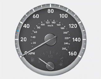
The speedometer indicates the speed of the vehicle and is calibrated in kilometers per hour (km/h) and/or miles per hour (MPH).
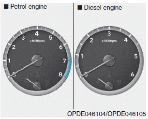
Tachometer

Copyright © 2025 www.hi30.net