Hyundai i-30: Intake and Exhaust System / Intercooler
Components and components location
| Comoinents |
| 1. Intercooler
assembly 2. Intercooler air guard 3. Intercooler inlet hose & pipe 4. Intercooler outlet hose & pipe |
5. RCV solenoid
hose B 6. RCV solenoid hose C 7. RCV hose |
Repair procedures
| Removal and Installation |
| 1. |
Disconnect the battery negative terminal.
|
| 2. |
Remove the engine cover.
(Refer to Engine and Transaxle Assembly - "Engine Cover")
|
| 3. |
Remove the air duct and air cleaner assembly.
(Refer to Intake and Exhasut System - "Air Cleaner")
|
| 4. |
Remove the battery.
(Refer to Engine Electrical System - "Battery")
|
| 5. |
Remove the Engine Control Module (ECM).
(Refer to Engine Control/Fuel System - "Engine Control Module (ECM)")
|
| 6. |
Remove the battery tray.
(Refer to Engine Electrical System - "Battery")
|
| 7. |
Remove the engine room under cover.
(Refer to Engine and Transaxle Assembly - "Engine Room Under Cover")
|
| 8. |
Remove the intercooler inlet hose and pipe.
|

| 9. |
Remove the intercooler outlet hose and pipe.
|
| 10. |
Remove the front bumper cover.
(Refer to Body - "Front Bumper Cover")
|
| 11. |
Loosen the radiator air guard mounting bolts (A).
|
| 12. |
Remove the radiator lower air guard (A).
|
| 13. |
Remove the intercooler assembly (A).
|
| 14. |
Install in the reverse order of removal.
|
 Air Cleaner
Components and components location
Comoinents
1. Air cleaner
upper cover
2. Air cleaner element
3. Air cleaner body
4...
 Intake Manifold
Components and components location
Components
1. Intake manifold
2. Throttle body gasket
3. Throttle body
4. Vacuum pipe & hose assy
5...
Other information:
Hyundai i30 (PD) 2018-2025 Owner's Manual: Changing a tyre with TPMS
If you have a flat tyre, the low Tyre Pressure and Position telltales will come on. We recommend that the system be checked by a HYUNDAI authorised repairer. CAUTION It is recommended that you do not use a puncture-repairing agent not approved by HYUNDAI dealer to repair and/or inflate a low pressure tyre...
Hyundai i30 (PD) 2018-2025 Service Manual: Seat Heater Switch
Components and components location Components [Front seat switch] 1. Driver seat heater switch 2. Assist seat heater switch Schematic diagrams Circuit Diagram [Front Seat Heater Switch(Driver)] [Front Seat Heater Switch(Assist)] Repair procedures Removal [Front Seat] 1...
Categories
- Manuals Home
- 3rd Generation i30 Owners Manual
- 3rd Generation i30 Service Manual
- Shift-lock system. Shift-lock release
- To activate the ISG system
- LKA system operation
- New on site
- Most important about car
Power windows
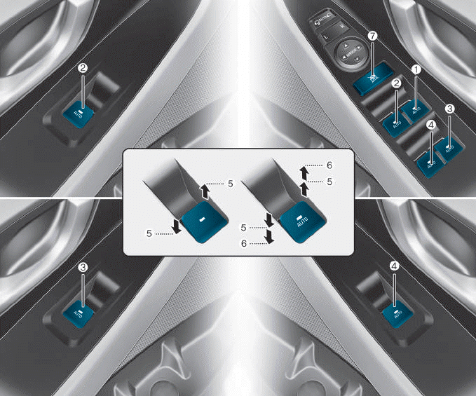
(1) Driver’s door power window
switch
(2) Front passenger’s door power
window switch
(3) Rear door (right) power window
switch
(4) Rear door (left) power window
switch
(5) Window opening and closing
(6) Automatic power window
(7) Power window lock switch

Copyright © 2025 www.hi30.net