Hyundai i-30: Rear Corner Radar System / Rear Corner Radar Unit
Hyundai i30 (PD) 2018-2025 Service Manual / Advanced Driver Assistance System (ADAS) / Rear Corner Radar System / Rear Corner Radar Unit
Specifications
| Specifications |
|
Items |
Blind-Spot Collision Warning (BCW) |
Blind-Spot Collision- Avoidance Assist-Rear (BCA-R) |
|
Rated voltage |
DC 12V |
|
|
Operating voltage |
9V - 16V |
|
|
Operating speed |
20 km/h - 255 km/h |
60 km/h - 200 km/h |
|
Sensible distance |
70m |
|
|
Curvature radius |
Start : More than 100m |
Start : More than 625m |
|
Stop : Less than 70m |
Stop : Less than 588m |
|
|
Frequency |
24 GHz |
|
|
Numbers |
2EA |
|
|
Items |
Rear Cross-Traffic Collision Warning (RCCW) |
Rear Cross-Traffic Collision- Avoidance Assist (RCCA) |
|
Rated voltage |
DC 12V |
|
|
Operating voltage |
9V - 16V |
|
|
Operating speed |
0 km/h - 10 km/h |
|
|
Sensible distance |
25m |
|
|
Curvature radius |
- |
|
|
Frequency |
24 GHz |
|
|
Numbers |
2EA |
|
|
Items |
Safe Exit Assist (SEA) |
|
Rated voltage |
DC 12V |
|
Operating voltage |
9V - 16V |
|
Operating speed |
0 km/h - 3 km/h |
|
Sensible distance |
25m |
|
Curvature radius |
- |
|
Frequency |
24GHz |
|
Numbers |
2EA |
Schematic diagrams
| Circuit Diagram |
[5Door]
[Wagon]
[Fastback]
Repair procedures
| Removal |
| 1. |
Disconnect the negative (-) battery terminal.
|
| 2. |
Remove the rear bumper cover.
(Refer to Body - "Rear Bumper Cover")
|
| 3. |
Remove the rear corner radar unit (A) after loosening the mounting nuts.
|

| 4. |
Replace the bracket (A) when the bracket is physically changed or damaged.
|
| Installation |
| 1. |
Install the rear corner radar unit and bracket.
|
| 2. |
Install the rear bumper.
|
| 3. |
Connect the negative (-) battery terminal.
|
| 4. |
Perform "Correcting the Blind-Spot Radar Unit Angle" procedures.
|
| 5. |
Perform "Rear Corner Radar Calibration" procedures.
|
| Adjustment |
Correction Overview
When you replace a rear corner radar bracket or components after a rear or side
collision of a vehicle equipped with the rear corner radar system, you need
to check if the mounting angle of the rear corner radar.
Check before Correction
| 1. |
When a failure code [C2702 (Master)] or [C2703 (Slave)] occurs, check
the following before performing correction.
|
| 2. |
Check the vehicle condition and whether the BSD unit or bracket is deformed
(mounting angle, twisted vehicle body, etc.).
|
||||||||||||
| 3. |
Check the nut tightening. Check if there is any foreign substance.
|
||||||
Correcting the Rear Corner Radar Unit Angle
| 1. |
After replacing the rear corner radar unit or bracket, with the bumper
removed, use the rear corner radar unit correction tool set (special
tool : 09985-3T500) to perform angle correction.
|


| 2. |
Attach a vertical plumb (special tool : 09958-3T010) on the hood, and
lower the plumb (A) to the ground so that it passes through the center
of the emblem.
|
| 3. |
Marking the center point below the plumb (A).
|
| 4. |
Attach a vertical plumb (special tool : 09958-3T010) on the trunk (or
tailgate), and lower the plumb (A) to the ground so that it passes through
the center of the emblem.
|
| 5. |
Marking the center point below the plumb (A).
|
| 6. |
Marking the center of vehicle by a string.
|
| 7. |
Mount the rear corner radar unit fixing adaptor (special tool : 09958-3T080)
on the rear corner radar unit and fix the level laser (special tool
: 09958-3T070).
|
| 8. |
Measure the angle (C) between the center line (A) of the angle measuring
plate and the horizontal laser beam (B) using a digital protractor (special
tool : 09958-3T090).
|
| 9. |
Use a digital inclinometer (special tool : 09958-3T100) to measure the
vertical angle of the rear corner radar unit.
|
| 10. |
Measure the horizontal and vertical angles of left and right rear corner
radar units. If the measured values deviate from the specified values,
insert a washer between the bracket of the rear corner radar unit.
|
| 11. |
After checking and correcting the rear corner radar unit angle, perform
the rear corner radar correction procedure.
|
Diagnosis with Diagnostic tool
| 1. |
Rear bumper accident vehicles and vehicles that replaced BCW units must
perform BCW unit alignment using Diagnostic tool.
|
| 2. |
Connect the cable of Diagnostic tool to the data link connector in driver
side crash pad lower panel, and turn on the Diagnostic tool.
|
| 3. |
Select the 'S/W Management' and 'Car model'.
|
| 4. |
Select "Blind -Spot Collision Warning" and "BSD Radar Calibration".
|
| 5. |
Perform the "BSD Radar Calibration" procedure according to the Diagnostic
tool screen message.
|
 Troubleshooting
Diagnosis with Diagnostic tool
1.
In the body electrical system, failure can be quickly diagnosed by using
the vehicle diagnostic system (Diagnostic tool)...
 Rear Corner Safety ON/OFF Switch
Components and components location
Circuit Diagram
Repair procedures
Inspection
1.
Disconnect the negative (-) battery terminal...
Other information:
Hyundai i30 (PD) 2018-2025 Service Manual: Fuel pressure test
Fuel Pressure Test 1. Release the residual pressure in fuel line. (Refer to Fuel Delivery System - "Release Residual Pressure in Fuel Line") • When removing the fuel pump relay, the diagnostic trouble code (DTC) will be occurred...
Hyundai i30 (PD) 2018-2025 Service Manual: Rear Cross Member
Repair procedures Removal 1. Loosen the wheel nuts slightly. Raise the vehicle, and make sure it is securelysupported. 2. Remove the rear wheel and tire (A) from the rearhub...
Categories
- Manuals Home
- 3rd Generation i30 Owners Manual
- 3rd Generation i30 Service Manual
- Light bulbs
- Engine coolant
- Brake/clutch fluid
- New on site
- Most important about car
Door locks
Operating door locks from outside the vehicle
Mechanical key
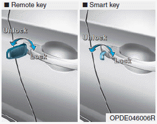
Turn the key toward the rear of the vehicle to unlock and toward the front of the vehicle to lock.
If you lock/unlock the driver's door with a key, a driver’s door will lock/unlock automatically.

Copyright © 2025 www.hi30.net