Hyundai i-30: Lubrication System / Oil Pan
Components and components location
| Components |
| 1. Oil Pan |
2. Drain Plug |
Repair procedures
| Removal |
| 1. |
Remove the engine room under cover.
(Refer to Engine and Transaxle Assembly - "Engine Room Under Cover")
|
| 2. |
Drain engine oil.
(Refer to Lubrication System - "Engine Oil")
|
| 3. |
Remove the oil pan (A).
Insert the blade of SST (09215-3C000) between the ladder frame and the
oil pan. Cut off applied sealer and remove the oil pan.
|

| Installation |
| 1. |
Install the oil pan.
|
| 2. |
Refill engine with engine oil.
(Refer to Lubrication System - "Engine Oil")
|
 Oil Pressure Control Solenoid Valve
Repair procedures
Removal
1.
Disconnect the negative battery terminal.
2.
Disconnect the oil pressure control solenoid valve wiring, and then
remove the oil pressure control solenoid valve (A)...
 Oil Level Gauge & Pipe
Repair procedures
Removal and Installation
1.
Remove the oil level gauge (A).
2.
Timing chain cover (A)...
Other information:
Hyundai i30 (PD) 2018-2025 Service Manual: Components and components location
..
Hyundai i30 (PD) 2018-2025 Service Manual: Repair procedures
Removal 1. Loosen the wheel nuts slightly. Raise the vehicle, and make sure it is securely supported. 2. Remove the front wheel and tire (A) from the front hub. Tightening torque : 107...
Categories
- Manuals Home
- 3rd Generation i30 Owners Manual
- 3rd Generation i30 Service Manual
- Scheduled maintenance services
- Shift-lock system. Shift-lock release
- Recommended lubricants and capacities
- New on site
- Most important about car
Turn signals and lane change signals
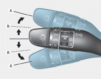
To signal a turn, push down on the lever for a left turn or up for a right turn in position (A). To signal a lane change, move the turn signal lever slightly and hold it in position (B).The lever will return to the OFF position when released or when the turn is completed.

Copyright © 2025 www.hi30.net